• This Forum is for adults 18 years of age or over. By continuing to use this Forum you are confirming that you are 18 or older. No content shall be viewed by any person under 18 in California.

Induction brass annealer redux

Frank....
This is just a guess, but I would say 2" from the outside diameter of the induction coil. Few years ago I had one builder run the coil through a metal front front plate, using rubber grommets to guide and insulate through the plate. Problem was the grommets were only 1/4" wide. Front panel got hot and the coil was not receiving full energy. Cut larger holes and replaced them with 2" grommets. All OK after that.
Hope this helps
Gina
Thank you Gina. I looked up proximity effects before I sent my note to you and I couldn’t find anything definitive - so it dawned on me that you might have some personal experience on this. Thank you. I plan to have clearances far greater than 2-inches in any case so I appreciate the reassurance
Frank
 
@SGK just a FYI, today I did a very unscientific test. I am in the process of doing a reshape / build on my flux concentrator annealer. its already in parts as the ZVS board has seen some serious heat issues and I think the capacitors are on their last legs... its been my try out unit for a lot of ideas and builds so has been abused.

Anyhow...... today I unwound the Litz wire, lowered the core on its mount and re wound the turns at the top ( continuous ) part of the core. ( six full turns). Powered it all up on a 2.5 sec burst, .308 case hardly got warm and I could hold it in my hand easily.

Later today I rewound it across the gap with six full turns. Powered up and burnt off 800F templaq in 2.5 secs.
( 4 to 5 A at 36 V ) only at the case neck and not down onto the shoulder.

This was a very basic test and I must admit even my old section of Litz wire is a bit jaded and fluffy, the pillars of the ZVS board are getting pretty warm at the same time ( BUT THIS WAS ALL WITH NO FANS OR OTHER COOLING )

But it does prove ( to my mind at least ) that the coil must be wound across the gap.
 
@kiwijohn Do you have a link to the core you're using? It would be interesting to know the material. Does the core get hot? My pillars stay pretty cool, even with heat sinks off - The litz wire gets warm but cools off quickly. I suspect the tinning process of the litz ends could cause hot spots towards the terminals. (varnish/insulation melted above the portion being tinned)?
 
@Standardelg here is a link to the core I used as posted earlier, under the specifications I found that it is made from.
MnZn PC40 Al 3750nH/N2
My Litz wire is .1 x 800

ferrite core

The core doesnt get hot, there is some warming due to transfer from the Litz, but no real build up. Yes I have seen that the terminal portion or just short of it has gotten hot. I did sleeve that region in heat shrink to provide more durability but that may have also provided a heat trap! It has since split and come away.

I have handled and reworked the coils quite a bit, sliding them on and off the core when I change it around, this hasnt helped.

I have a spare piece of Litz that I am sleeving in heat resistant p;astic expanded mesh, if I change from that idea I may have it dipped at a motor rewind shop, in the varnish? they use.

One of my terminal post sets is getting a lot hotter than the other which leads me to suspect that the capacitors towards that side are starting to fail. I am going to desolder them and try some other ones of the same value.
I dont know what success I will have desoldering the board, I suspect it will be a PITA.
Thanks, it's PC40, and available from various sellers on Ali :) Some with 14d delivery time. Think I'll order some.

The problem with the melted varnish is if the varnish on the individual strands have melted above the tinning area. Clamping on some sort of heat sink around the wires when dipping the ends in the solder pot prevents this. Keeping the tinned portion short also helps. If the individual strands touch eachother with the insulation melted off, that part of the wire will not work as a Litz wire, and you will get heat as a result of skin and proximity effects. That could easily be the cause for one side heating up more. (I also think going for slightly smaller strands would help - rule of thumb is 0.08 for 100kHz?) I have a few metres of 2000 strands 0.1mm and also 0.08x660 - will test them (and compare with the 0.04x3000 I'm using now) some day when I get in the mood for tinning litz wire.
I have received several boards with caps broken off during transport. Often a cap or other component has a bad solder joint - you can feel the legs wiggling in the joint.While you're at desoldering, then you could also apply thermal paste between mosfets and heatsinks (they are hard to get at without desoldering).

When it comes to replacing parts - read an interesting article on Fluxeons blog. Replacing the mosfets with more expensive silicium carbide versions should make a big deal. https://fluxeon.com/blogpost/278/
That would be a fun experiment.
 
The benefit comes from reduced Rds(On) of the MOSFET. The eBay induction boards typically use Infineon's IRFP260N https://www.infineon.com/dgdl/irfp260npbf.pdf?fileId=5546d462533600a401535628a2ef1fe4 which has an Rds(On) on 40 milli ohms. That's quite low. But SiC MOSFETs can halve this value (and also thereby help increase the SOA of the device). They're very expensive though. An IRFP260N will cost you $3.04 in quantities of 1 from Mouser. A SiC MOSFET will run you 10x that cost.
 
With respect to the experiments Patrice is doing, it may be worthwhile, if someone nearby has an AMP, that they anneal some cases from Patrice using the AMP. Compare the results from an AMP versus a home built annealer to see if there is any real variance between them.
Hello,
Soon I'll get from a friend some 6 PPC cases (with a .262 neck as mine) annealed with an AMP machine. These cases have been fired many many times. He'll also provide me some unannealed cases (same caliber of course) for comparison.
I'll go then to university for giving a vickers hardness test on AMP annealed cases and on unannealed ones.
I'll report all results as soon as I can with graphs.
6 PPC is for sure a challenge for annealing cause the necks are very very thin.
I really look forward what AMP can do with those cases.
Then I'll be able to compare the differences in annealing quality with AMP and my home made annealer.
Don't worry you'll get all results.
II would like to show you a video showing how the collars turn red with 2.8 seconds annealing. They turn red very red and hardness is ok.
Unfortunately I can't upload it. WHY? .MP4 extension!!!!!!!!!!!!!!!!!!!!!!!!. I have no idea. Any idea would be wellcome
Regards to everybody
Patrice
 
Patrice

This is really good work. However I'd like to see things standardized and controlled a little better. Take, for example, 3 virgin (unfired) pieces of brass of one caliber. Measure these and show us where these points are on the brass (as you did here). We have a baseline for comparison. Shoot these same cases, say, 5 times and measure again with consistency of measurement points. Show the comparison graphically (perhaps you average the cases at each measurement point for these types of comparisons). Now we see how firing work hardens the brass. Then anneal showing the impact to Tempilaq color change. Show us how these cases sat in the work coil. (When I'm annealing I make sure your point 7 or 8 - one shoulder width down the case wall - is in the middle of my work coil even if it means the mouth of the case is poking out the top. To your post #2305 I would probably be saying 'move the cases higher in the work coil and maintain the higher anneal times.) Measure again and present the comparison. For each annealing scenario you will need to show those same cases throughout the virgin->fired->annealed process and their measurements so start with enough cases to allow enough annealing testing. I also think you need a few data points (3 or 4?) around the circumference of the case at each measurement 'point' with these then averaged to average out imperfections in the brass thickness and - importantly - imperfections in the placement of the brass in the centre of the work coil. This would be most relevant on the unturned portions. (I ended up adding inserts in my shelf design to make sure the brass was more accurately centered in the coil.)

(You could do a little testing beforehand to narrow down some of the scenarios you eventually put through the whole test.)

I'm not sure you're heading in the right direction re modifying your work coil. As you are finding, dealing with the neck is much easier than dealing with the shoulder. And you don't want too cook the neck trying to get the shoulder right. (I have pushed it too hard before and the neck brass got so soft that I could squeeze the neck closed between thumb and forefinger.) Ideally we need concentrated application of current at the shoulder/body junction (and relatively fast annealing times). This is where the air-gapped ferrite core work coil comes into its own (and I am not surprised that AMP use this. The work coil in the GinaErick design is not well suited to annealing cartridge brass but it is easy for people to construct. I'm not sure that your proposed modifications to the work coil achieve what you are after but designing work coils is an electronics skill in itself. Maybe you know the induction field and eddy current effects of what you are doing.

One other suggestion. We believe that AMP's Aztec feature monitors current to determine the point when the brass gets too hot (and softens dramatically). Current increases steadily as the brass in the work coil heats but then collapses when it gets too hot. Previously in this thread I have posted a link to work done by one builder which plots this sudden drop in current. This 'destruction of a case' test allows Aztec to determine this point in time for a given case batch. From there they back off 'just enough' with that formula testing via Vickers hardness testing. If you can integrate this current monitoring into your build you will be much closer to determining a method for optimal annealing time that doesn't require you to go back to Vickers testing for each batch of cases you wish to anneal.

Regards

Steve
Thanks Steve
Long reply
I really appreciate your comments
Soon I'll have more time to answer you.
I'll post some pics of my prototype annealer with centering bushings and everything. You'll see also the case position in the coil I used for hardness tests.
Best regards
Patrice
 
Hello,
Soon I'll get from a friend some 6 PPC cases (with a .262 neck as mine) annealed with an AMP machine. These cases have been fired many many times. He'll also provide me some unannealed cases (same caliber of course) for comparison.
I'll go then to university for giving a vickers hardness test on AMP annealed cases and on unannealed ones.
I'll report all results as soon as I can with graphs.
6 PPC is for sure a challenge for annealing cause the necks are very very thin.
I really look forward what AMP can do with those cases.
Then I'll be able to compare the differences in annealing quality with AMP and my home made annealer.
Don't worry you'll get all results.
II would like to show you a video showing how the collars turn red with 2.8 seconds annealing. They turn red very red and hardness is ok.
Unfortunately I can't upload it. WHY? .MP4 extension!!!!!!!!!!!!!!!!!!!!!!!!. I have no idea. Any idea would be wellcome
Regards to everybody
Patrice
with ...tube of course:
Many people claim that you must not turn the neck red. because it could be over "cooked".
Give a look at this diagram. I've measured vickers hardness after annealing with this duration.
As you can see a part of the neck is not enough annealed even if it turned red. This is position 3.
Of course shoulder is too hard on positions 4 and 5.

1614374008915.png

 
That sure was red! The zone most of us thought we weren't supposed to go. So, for those of us that have a (non AMP) induction annealer and no access to a hardness testing instrument what are we supposed to do? How are we supposed to know we're doing the right thing?
 
I always wondered about the get your brass too red hot you will harm the alloy.
When they melt the two metals to create the alloy is that not hotter than cherry red?
 
That sure was red! The zone most of us thought we weren't supposed to go. So, for those of us that have a (non AMP) induction annealer and no access to a hardness testing instrument what are we supposed to do? How are we supposed to know we're doing the right thing?
I think the whole point of annealing is two things.. (1.) Keep the necks from splitting, and (2.) Manage neck tension and springback after sizing to assure all neck diameters stay uniform. Only time will tell for first goal, but second goal is easier to check - just buy a few pin gages from amazon and measure inside diameters of your finished necks for uniformity. I also turn my necks to uniform thickness and use a Forcepak pressure gauge on my K&M arbor press to make sure all my bullet insertion pressures are uniform - but I find that comes naturally if necks are uniform and chamfered. Good luck to you!
 
Last edited:
That sure was red! The zone most of us thought we weren't supposed to go. So, for those of us that have a (non AMP) induction annealer and no access to a hardness testing instrument what are we supposed to do? How are we supposed to know we're doing the right thing?
Hello
Soon I'll receive tempilaq ranging from 750F to 1300F.
I'll see if I can find a correlation between vickers hardnes test and one of the tempilaq temps.
Would Be perfect if I find something.
For sure I'll let you know the results of my tests.
 
@SGK, @Standardelg ...been away on vacation myself, thanks for the replies. I have ordered a new ZVS board, this one you can assemble yourself and is pretty cheap to buy, but lord knows when it will get here, I thought for the cost it would be a good standby / back up. I may well just get better Mosfets and paste etc prior to assembling it. I also wonder about applying the Caps staggered ... as the bank of three, sit side by side, maybe the middle one of the three caps could be applied to the other side of the pcb? and in the second row reverse that?
I have access to copper sheeting that I can cut strips off to form the post attachments. i will make up some heat sinks for when I make the new coil, ( I have a meter of the 880 strand Litz wire left )

Scroll across to the last photo to show the DIY kits

DIY kit annealer board
 
Hello,
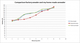
Today I could test vickers hardness (HV) on 6 ppc annealed cases sent by a friend of mine.
He used a popular annealing machine recently purchased.
Unbelievable, I obtained exactly the same results with my home made annealer.
I used Gina Eric design for the coil, no ferrite core, no pulse, nothing complicated and the result is amazing for me. So I'm going to kill another myth.
A simple coil (8 turns) (1/8" copper tubing) as the one designed by Gina Eric works perfectly.
I didn't test on other calibers because it's time consuming, really!!!.
You can give a look to the graph below and you'll see that the curves are superimposed almost perfectly.
As the PPC case has a very thin neck, it's very difficult to heat the shoulder. I'm pretty proud with my results.
I think that next week tempilaq will be home, I'll conduct tests and I'll let you informed about the results.


1614891520756.png
 
@SGK, @Standardelg ...been away on vacation myself, thanks for the replies. I have ordered a new ZVS board, this one you can assemble yourself and is pretty cheap to buy, but lord knows when it will get here, I thought for the cost it would be a good standby / back up. I may well just get better Mosfets and paste etc prior to assembling it. I also wonder about applying the Caps staggered ... as the bank of three, sit side by side, maybe the middle one of the three caps could be applied to the other side of the pcb? and in the second row reverse that?
I have access to copper sheeting that I can cut strips off to form the post attachments. i will make up some heat sinks for when I make the new coil, ( I have a meter of the 880 strand Litz wire left )

Scroll across to the last photo to show the DIY kits

DIY kit annealer board
Some on the underside might help but most of the heat gets transmitted into the board plating and radiates from there. You don't need to use thermal paste. It looks like they're supplying thermal pads (although I have no idea of the thermal coefficient of the pads they're supplying). The Mosfets they are supplying are quite good. It will cost you a LOT more to better them.
 
Hello,
Today I could test vickers hardness (HV) on 6 ppc annealed cases sent by a friend of mine.
He used a popular annealing machine recently purchased.
Unbelievable, I obtained exactly the same results with my home made annealer.
I used Gina Eric design for the coil, no ferrite core, no pulse, nothing complicated and the result is amazing for me. So I'm going to kill another myth.
A simple coil (8 turns) (1/8" copper tubing) as the one designed by Gina Eric works perfectly.
I didn't test on other calibers because it's time consuming, really!!!.
You can give a look to the graph below and you'll see that the curves are superimposed almost perfectly.
As the PPC case has a very thin neck, it's very difficult to heat the shoulder. I'm pretty proud with my results.
I think that next week tempilaq will be home, I'll conduct tests and I'll let you informed about the results.


View attachment 1239352
But that begs the question I posted quite some time ago about the validity of your "expected values" curve. Your prior tests and comments suggesting "not enough annealed" would appear to be invalidated if the annealing of this popular, recently purchased, annealer is correct. Consider position 3 when heated to glowing red (post 2370) - it went to circa 120 Vickers HV. Factory annealer pins that closer to 128 (post 2377). The manufacturer would argue that your target is incorrect.

We need two things: (1) a target that is valid with respect to metallurgy plus (2) - and why your Tempilaq vs hardness tests are so important - a readily useable measurement stick. But you've got to have (1) right first.
 
Last edited:

Upgrades & Donations

This Forum's expenses are primarily paid by member contributions. You can upgrade your Forum membership in seconds. Gold and Silver members get unlimited FREE classifieds for one year. Gold members can upload custom avatars.


Click Upgrade Membership Button ABOVE to get Gold or Silver Status.

You can also donate any amount, large or small, with the button below. Include your Forum Name in the PayPal Notes field.


To DONATE by CHECK, or make a recurring donation, CLICK HERE to learn how.

Forum statistics

Threads
165,037
Messages
2,188,519
Members
78,645
Latest member
Kenney Elliott
Back
Top