• This Forum is for adults 18 years of age or over. By continuing to use this Forum you are confirming that you are 18 or older. No content shall be viewed by any person under 18 in California.

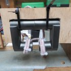
Induction brass annealer redux

One issue with such ferrite cores is that they tend to be expensive and hard to find in the 'right' shape. It's no wonder the ones AMP uses are custom made for them. One solution is to buy a toroidal shaped one and cut the gap but the stuff can be very brittle. At the end of the day, experimenting with this stuff can add up for a build count of one.
 
If using a “conventional” coil design I wonder if either of these orientations would work. On the left the thought was to have tight coupling with the shoulder body junction and a greater space for the neck so that all heats more evenly. On the right there would be tight coupling from neck to body/shoulder area.
(I meant flip the drawing.)
1613662622581.jpeg
 
I think you will find that as you shrink the diameter of the coil you lose a lot of coil inductance. Here is a link to an online calculator for air core inductors which is what the conventional work coil is.


Roughly speaking a tightly wrapped coil of 8 turns around 0.75" outer diameter tubing yields a coil diameter of 1", 1.25" long and 8 turns. So circa 1uH.

The goal is to have a 'tighter' field at the shoulder area (and conduction will likely take care of the neck). More turns across a narrower length requires thinner wiring and presents cooling issues. One could try making a coil out of Litz Wire but I think the much better strategy is to deploy an air gapped ferrite approach. (Obviously we need the air gap to have a place to slide the case into.)
 
My solution. I posted before I saw you don't have a 3D printer. I have only test fitted it but it does work. I will take some actual photos when I get home.


View attachment 1235141View attachment 1235144
Here’s a couple ideas. 1) if you have a 3D printer I’d be happy to pay you to print it and send me a set. If not and you have the file, I can go on thing verse and see if I can find someone to print it. So your thought isn’t waisted. Btw here’s my email for a better response. iwdpo@gmail.com thank you for your help your my rock star today
 
@SGK since you know where te North Island is I can say Bay of Plenty.

The litz wire wrap is 800 strands and the core is 20 mm diameter with 2 1/2 winds each side of the gap..

I was going to do how you drew the diagram, but was advised to have the turns as close to the air gap as possible.

I am just a trial and error guy, I've toasted my share of parts, especially on the gapped build.

Re the helical style coil from Litz wire, it would need a lot of air cooling ( fans ) I have seen the number of turns I use get pretty hot ( like when a relay fries closed )

PS I am coming over to Napier next week, should catch up for a beer.
 

Attachments

  • IMG_4945.JPG
    IMG_4945.JPG
    535 KB · Views: 122
Last edited:
Gina,
I need to ask a basic question, and I apologize if this has been answered before.
One layout constraint I expect is to keep the induction coil and induction card away from anything metallic - because I know that any nearby metal will impact the magnetic field (and more so if those metals happen to be ferrous).
Can you please advise a minimum clearance distance from the induction coil to other metals?
Thank you.
Frank from Indianapolis (another retired power engineer)
 
@SGK
Further thoughts from your comment.
The shoulder has more mass. So needs more heat either by more current or more time.
The existing power supply is (more than) adequate
Higher current in one area has a lot of discussion. So this is hard or complicated.
More time is easier. This just requires some calibration runs for time.
Other issues maybe field collapse.
A short interruption to engage / reengage the field can be adjust out.
At least from a concept it looks doable.
 
hello everyone
just a question
where do you find the ferrite cores?
how do you determine the diameter of it and their spacing?
cordially
 
@SGK

I was going to do how you drew the diagram, but was advised to have the turns as close to the air gap as possible.


PS I am coming over to Napier next week, should catch up for a beer.

I'm now living in Miami so a beer would be difficult. I wish I was in NZ right now with the roar about to kick off.

Who advised re having the turns as close to the air gap? I've not seen anything to suggest that's necessary. I also wonder what frequency that things oscillates at...

Does your ferrite core get hot?

I would wrap the Litz wire with Kapton tape to stop it from absorbing heat from the hot case.
 
Last edited:
Here you can see the AMP's work coil being assembled. Watch from about 3'40 onwards.


And here is a pic. Note the Kapton tape shielding the Litz wire where it gets close to where the hot case will be and what appears to be a temp monitor strapped to the ferrite (covered in Kapton tape). What appears to be a resistor bank is possibly for measuring current accurately. That ferrite would not be cheap.

AMP.png
 
At this link LR88 posted his results from monitoring current versus temp and time. I hope he doesn't mind me reposting his results here (again).

X axis -> 1/10 sec
red -> drawn current
blue -> coil temperature
orange -> voltage
A clear maximum at melting point.

300-winmag-png.1120748


@jthor had previously noted that Aztec brings the case to the point of melting (destruction) "which is 915C or 1679F for C26000." At curie the current draw collapses because the resistance of the load (the case) changes abruptly. Aztec likely calculates the time to curie and provides an anneal time that backs things off from there. How much, we have no idea. Note that it took 800W of power to hit melting. That's more than most builds here can deliver.

LR88's example was for a 300 Win Mag case. If we just say it hit Curie at 13 secs (eyeballing the chart), given the linear nature of the change in current we can determine the required anneal time for a temp of brass. If room temp is 75F and Curie is 1679F, then hitting, say, 750F will take 5.47 seconds on his annealer.

From AMP's website:

Once a sacrificial case is inserted and "Start” is pressed, AZTEC "Analyse” mode applies a continuous and precise amount of power to the targeted zone of the case until the exact instant that a datum point is reached. In general terms, the longer it takes to reach the datum, the greater the mass of brass in the targeted zone. The capture is extremely accurate and reliable. A patent is pending. By referencing the datum point, AZTEC calculates the correct annealing setting. The calculation, or algorithm, varies from cartridge to cartridge. Extensive laboratory micro-Vickers hardness testing has determined these algorithms.
 
Last edited:
@SGK pitty about the beer, never mind. I had the standard coil measured at around 90 HZ and 3V A/C at the posts. Havent gotten around to measuring the ferrite unit. The core gets warm but it has a lot of mass.
To bond the Litz wire for a serviceable connection to the ZVS I melted solder into a .22 case, plunged in the prepped ends. Then crimped the shell case and made a connection plate for the 4MM stand offs out of sheet copper

The AMP unit shows 5 full turns and two part turns, thats two up from my unit. I cant recall he said to have them close to the gap....... I had wanted to do a continuous wrap of 5 or so turns on the ferrite body, like when winding an aerial.
My thinking was induction is induction shouldnt matter where on a continuous work piece, but was strongly urged to place it across the gap. Which is a PITA as you have to create a height that the case can pass under.
I have burned the silk(?) layer on the Litz coil with the mouth of case. This will cause the wire to arc at that point when the brass gets too close, a layer of insulation tape alleviated this. I might look into some kapton tape instead!


I would like to see the face of the work coil on the AMP unit.
I have seen folk build them with a bevel to give an even distance from the shell case, as the shoulder shapes away from the neck, but I think this is a wrong move because the case is thicker in the shoulder so by having the coil face closer at this point ( by not shaping it ) is of benefit in as much as the energy transfer happens here first across the narrower gap.
Cases ALWAYS appear to heat from the top ( mouth ) down regardless of induction method, maybe thats a reason that AMP put their cases in mouth down?

I see too that the cores are dunked in the same solution used for motor windings as well.... that ferrite core they use is massive! I wonder if thats so they achieve 50 BMG annealing.
 
Last edited:
The AMP's ferrite is a simple u shape. You can see this in the shape of the injected molding part used to hold it. (See just a moment after it falls into the basket in the vid above.) If the air gap isn't consistent across the face of the core you get into the peculiarities of 'stepped air gapped cores'. Note they have another part which appears to be hollowed out which fits in the air gap. I have presumed this is just a non-magnetic/conductive part to act as a heat shield so the ferrite doesn't absorb heat from the case. See, for example, 3'40 or 4'04 in the vid.
 
With respect to the experiments Patrice is doing, it may be worthwhile, if someone nearby has an AMP, that they anneal some cases from Patrice using the AMP. Compare the results from an AMP versus a home built annealer to see if there is any real variance between them.
 
Gina,
I need to ask a basic question, and I apologize if this has been answered before.
One layout constraint I expect is to keep the induction coil and induction card away from anything metallic - because I know that any nearby metal will impact the magnetic field (and more so if those metals happen to be ferrous).
Can you please advise a minimum clearance distance from the induction coil to other metals?
Thank you.
Frank from Indianapolis (another retired power engineer)
Frank....
This is just a guess, but I would say 2" from the outside diameter of the induction coil. Few years ago I had one builder run the coil through a metal front front plate, using rubber grommets to guide and insulate through the plate. Problem was the grommets were only 1/4" wide. Front panel got hot and the coil was not receiving full energy. Cut larger holes and replaced them with 2" grommets. All OK after that.
Hope this helps
Gina
 
One issue with such ferrite cores is that they tend to be expensive and hard to find in the 'right' shape. It's no wonder the ones AMP uses are custom made for them. One solution is to buy a toroidal shaped one and cut the gap but the stuff can be very brittle. At the end of the day, experimenting with this stuff can add up for a build count of one.
ferrite coils are awesome. Currently using one in one of my designs. Folks, cutting these are not too bad, but you have to do it right.


1) only buy a ferrite w/ a paint coating. This reduces chipping
3) tape the cutting edge to help reduce chipping
2) Use a tile saw (w/ water) and with a good blade

done. That's my tip of the week. ;)
 
Measuring points on my cases.


Here now my different annealing test with my home made machine.
As I use neck turned cases with very thin walls, (.262 neck) you'll see that in the shoulder area all my tests show a hardness level a bit too high. I'll try later to modify my coil. Actually I use Gina Erik design. I'll try to keep 8 turns but I'll reduce the height by superposing 3 coils over the 5 remaining. They will be superposed on the bottom part of the coil.

First test with 3.0 sec time annealing.
Conclusion:
The neck is too soft and the shoulder area is too hard

View attachment 1234884

Next test with 2.9 sec
Postions 1 and 2 on the neck are ok and the shoulder area is still too hard. This is that time that I'll use since I did ot make a new coil.


View attachment 1234887


Next test with 2.8 sec.
Position 1 on the neck is perfect but as you go back to the body, hardness's growing very fast in the shoulder area again.
What I can say about red glow on the neck. In a dark room, all the enck portion becomes very red. Soon, I'll receive tempîlaq and I'll try to find a correlation with my hardness tests.


View attachment 1234888

I've made a last test with a shorter time. Coming soon......
this is awesome. thanks for sharing. keep the observations coming!
 
Frank....
This is just a guess, but I would say 2" from the outside diameter of the induction coil. Few years ago I had one builder run the coil through a metal front front plate, using rubber grommets to guide and insulate through the plate. Problem was the grommets were only 1/4" wide. Front panel got hot and the coil was not receiving full energy. Cut larger holes and replaced them with 2" grommets. All OK after that.
Hope this helps
Gina
I built a case from folded sheetmetal ( actually roofing iron flat sheet, before it gets roller formed ) the hole in the front panel was just big enough to pass the coil through, I applied a grommet type rubber edging to it.
It was probably a 40mm elongated hole.

My first Gina design copy use ACM panel ( two thin sheets of ali with a plastic composite in between ) that used 8 mm holes for each copper leg to pass through, insulated with short sections of pvc tubing ( left over from the radiator / pump runs ) both appeared to have no parasitic losses.

Ferrite cores need not be expensive but may take a while to arrive these days. Rather than cut a round toroid i just ground down two of the "legs" on two c shaped cores.
cores via ali express
 
Last edited:
ferrite coils are awesome. Currently using one in one of my designs. Folks, cutting these are not too bad, but you have to do it right.


1) only buy a ferrite w/ a paint coating. This reduces chipping
3) tape the cutting edge to help reduce chipping
2) Use a tile saw (w/ water) and with a good blade

done. That's my tip of the week. ;)
I spent 2 days hacking through my first ferrite.

Bought a diamond disc for my dremel - and now it's like cutting butter.

If you cut it dry, wear a mask and eyeprotection. Do it outside or use a vacuum-cleaner or other good suction - dust will go literally everywhere, and you (and probably your lungs) will look like you've been working in a coal mine.
 

Upgrades & Donations

This Forum's expenses are primarily paid by member contributions. You can upgrade your Forum membership in seconds. Gold and Silver members get unlimited FREE classifieds for one year. Gold members can upload custom avatars.


Click Upgrade Membership Button ABOVE to get Gold or Silver Status.

You can also donate any amount, large or small, with the button below. Include your Forum Name in the PayPal Notes field.


To DONATE by CHECK, or make a recurring donation, CLICK HERE to learn how.

Forum statistics

Threads
165,431
Messages
2,195,916
Members
78,918
Latest member
Blassiter
Back
Top