
You are using an out of date browser. It may not display this or other websites correctly.
You should upgrade or use an alternative browser.
You should upgrade or use an alternative browser.
Induction brass annealer redux
- Thread starter Gina1
- Start date


Hello SGK, Is the offer to provide the parts for your case feeder still open? MachdoggyThanks. I have tried to make this relatively versatile so others can use it in their builds if they want. Obviously the clear drop tube can be as long as needed. The unit can reach over the front panel of a GinaErik build by up to 5.5cm (a little over 2 1/8") for alignment with a work coil. It has a footprint of 10" wide and up to 8.5" deep (if the drop tube only just overhangs the front panel and so less if extended more). Parts are available from eBay/Amazon etc and the 3D printed or laser cut acrylic parts can be ordered via me. (I would just print/cut the designs and have them ship directly. Not looking to make money out of this, just cover costs. I use Ponoko to cut the acrylic parts and a particular provider from 3dHubs to do the 3D printing. The 3D printing quality via HP's jet fusion technology is awesome and simply not comparable with FDM printing which can't print the drop shoot part anyway.) Some people might want to fashion their own base but I recommend getting the other parts done via these providers. If someone wants to make their own pedestal and clamp to fit I can help with the required design geometry but frankly it isn't costly to have them printed (when compared to the time required to make them). The printed drop shoot is a complex design. I had to model the entire unit in order to get it right.
What work is required to make this?
1. The biggest thing is drilling the motor mounting and rear pedestal holes and cutting the drop aperture in the hopper (cake tin). The motor mounting plate can be used as a stencil for the former once you have the centre of the hopper (which a couple of speed squares will do for you). A step drill bit is needed to drill out the hole for the motor shaft. A hand fret saw or similar and file is needed for the drop aperture. Measuring out the holes for the pedestal isn't hard.
2. The motor mounting plate (a 3mm acrylic disc sitting on the inside of the hopper and used to clamp the motor to the hopper) needs its holes to be countersunk. The motor requires M3 screws and so the countersinking bit ought to be 90 degrees.
3. Each feeder disc has a motor shaft coupling which attaches to the disc via 4x 6-32 screws and the holes in the acrylic disc need countersinking (82 degree).
4. Some bits need to be glued/welded together. I recommend using solvent welding and you can buy this stuff on Amazon
5. The clear drop tube needs to be cut to length
That's it.
What's needed for it to work?
The motor needs a 12V supply. You also need a mechanism for turning the motor off when a case is in the work coil (else it would keep feeding cases). I use an IR switch in my shelf and a control board which, amongst other things, controls the supply of 12V to the feeder motor. There are lots of ways to skin this cat, but if anyone wants to use my control board I have spare PCBs.
Any questions? Just ask.
Hello French redneckI'm sorry, I'm a French, I translate with google. Hello everyone, I came to seek information in the year 2019 , Since then I have progressed on my own machine. I recommend this (look at the whole aliexpress page) maximum 68 Volts 45 Amps
The temperature of 65 ° c (T ° MOFSET) stops the current. A short circuit cuts off the current. An external switch is possible (on/off). I added 26x0.27uf= 6,50uf. My winding is 6 turns + 5 turns (2 layers) not the work coil black it is too wide, the whiteView attachment 1233282
My actual work coil is 6tours + 5tours (2 layers) The inside diameter is 32 mm. I get a frequency of 28Khz The machine gives 1000w with a 20A 40V power supplyView attachment 1233280
I added a radiator, two fans but it is possible to put your finger in the water (down 50 ° c)
View attachment 1233284
A product seller site (read the whole page)

95.84US $ 5% OFF|2000W ZVS High Frequency Induction Heater Module Flyback Driver Heater Good Heat Dissipation +Coil+pump +power Adapter+crucible|Magnetic Induction Heaters| - AliExpress
Smarter Shopping, Better Living! Aliexpress.comwww.aliexpress.com
I'm going to do another work coil, but as the weather is nice, I'm going to go back and shoot. Between Belleau woods and Argonne where the boys came in 1917
View attachment 1233287
Nice to hear from a French guy. I'm not the only French on this amazing forum.
Je ne suis pas le seul Français donc ici sur ce forum.
Your rifle reminds me something. F1 or F2?
Best regards from Toulouse
Patrice
HelloLooking forward to the results. Remember, most target a color change in Tempilaq from green to grey-green (i.e. hits 750F) well below the shoulder-case wall junction. Everything above that - including the neck - gets MUCH hotter because it is materially thinner.
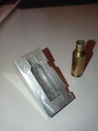
I've finally got acces to the laboratory in university in my city. As I'm a mechanics teacher, My friens let me access to the Vickers tester.
The load used on the vickers tester was 500 grams.
I could make many many test on my annealer and I could also test virgin lapua brass and many times fired brass also. Like this I could see if my procedures were reliable with virgin cases.

On those virgin cases I didn't test hardness on the shoulder area. Because I had no support correctly matching the shoulder area. I made a molding only for fireformed brass on 6 PPC.
Here's the test I made on 2 cases, 220 Russian Lapua virgin brass. You can compare to expected (attendu) results (grey line). The hardness on those virgin cases is ok
I didn't test more cases as I saw that the results matched expected results.
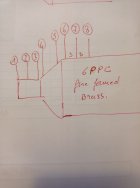
The measured points 1 to 3 are on the neck (from neck to shoulder) and points 4 to 6 are on the body behind the shoulder

I've tested hardness on many many times fired cases. I only tested the neck (positions 1 to 3) The caliber is 6 PPC with a .262 " neck. As you can see brass is work hardened and all the areas are far away from expected results.

As I can't post more images, I come back later. I'll show you my tests made with my home made annealer.
Looking forward to the results. Remember, most target a color change in Tempilaq from green to grey-green (i.e. hits 750F) well below the shoulder-case wall junction. Everything above that - including the neck - gets MUCH hotter because it is materially thinner.
Attachments

Measuring points on my cases.Hello
I've finally got acces to the laboratory in university in my city. As I'm a mechanics teacher, My friens let me access to the Vickers tester.
The load used on the vickers tester was 500 grams.
I could make many many test on my annealer and I could also test virgin lapua brass and many times fired brass also. Like this I could see if my procedures were reliable with virgin cases.
View attachment 1234870
On those virgin cases I didn't test hardness on the shoulder area. Because I had no support correctly matching the shoulder area. I made a molding only for fireformed brass on 6 PPC.
Here's the test I made on 2 cases, 220 Russian Lapua virgin brass. You can compare to expected (attendu) results (grey line). The hardness on those virgin cases is ok
I didn't test more cases as I saw that the results matched expected results.
The measured points 1 to 3 are on the neck (from neck to shoulder) and points 4 to 6 are on the body behind the shoulder
View attachment 1234864
I've tested hardness on many many times fired cases. I only tested the neck (positions 1 to 3) The caliber is 6 PPC with a .262 " neck. As you can see brass is work hardened and all the areas are far away from expected results.
View attachment 1234878
As I can't post more images, I come back later. I'll show you my tests made with my home made annealer.
Here now my different annealing test with my home made machine.
As I use neck turned cases with very thin walls, (.262 neck) you'll see that in the shoulder area all my tests show a hardness level a bit too high. I'll try later to modify my coil. Actually I use Gina Erik design. I'll try to keep 8 turns but I'll reduce the height by superposing 3 coils over the 5 remaining. They will be superposed on the bottom part of the coil.
First test with 3.0 sec time annealing.
Conclusion:
The neck is too soft and the shoulder area is too hard

Next test with 2.9 sec
Postions 1 and 2 on the neck are ok and the shoulder area is still too hard. This is that time that I'll use since I did ot make a new coil.

Next test with 2.8 sec.
Position 1 on the neck is perfect but as you go back to the body, hardness's growing very fast in the shoulder area again.
What I can say about red glow on the neck. In a dark room, all the enck portion becomes very red. Soon, I'll receive tempîlaq and I'll try to find a correlation with my hardness tests.

I've made a last test with a shorter time. Coming soon......
Attachments

I always got great results from salt bath annealing, but now I’m considering building the basic GinaErick induction annealer because it seems more convenient to use. I never considered an induction annealer before because I didn’t want to spend a stupid amount of money on it - but obviously that’s not the case here. It looks like a fun project. Thank you for making the design public.
Hello.I always got great results from salt bath annealing, but now I’m considering building the basic GinaErick induction annealer because it seems more convenient to use. I never considered an induction annealer before because I didn’t want to spend a stupid amount of money on it - but obviously that’s not the case here. It looks like a fun project. Thank you for making the design public.
Easier to use an induction annealer than the salt bath and pretty much more safe of course.
You'll have to spend a lot of time. Regarding the money, I spent approximately 600.00 euros for everything but mine has an auto feeding system wich is not necessary.
Concerning the quality of annealing with salt bath, AMP tested this system and it appears that it can't reach the hardness level expected. Cases are not fully annealed. You can give a look at this address :

Salt Bath Annealing - Does It Work? | Learn More | AMP
View the latest articles from AMP Annealing. Get tips and tricks from our R&D. Here we upload articles to provide your the best possible information on innovations in the annealing process.
 www.ampannealing.com
Patrice
I'm going to kill a myth.Measuring points on my cases.
Here now my different annealing test with my home made machine.
As I use neck turned cases with very thin walls, (.262 neck) you'll see that in the shoulder area all my tests show a hardness level a bit too high. I'll try later to modify my coil. Actually I use Gina Erik design. I'll try to keep 8 turns but I'll reduce the height by superposing 3 coils over the 5 remaining. They will be superposed on the bottom part of the coil.
First test with 3.0 sec time annealing.
Conclusion:
The neck is too soft and the shoulder area is too hard
View attachment 1234884
Next test with 2.9 sec
Postions 1 and 2 on the neck are ok and the shoulder area is still too hard. This is that time that I'll use since I did ot make a new coil.
View attachment 1234887
Next test with 2.8 sec.
Position 1 on the neck is perfect but as you go back to the body, hardness's growing very fast in the shoulder area again.
What I can say about red glow on the neck. In a dark room, all the enck portion becomes very red. Soon, I'll receive tempîlaq and I'll try to find a correlation with my hardness tests.
View attachment 1234888
I've made a last test with a shorter time. Coming soon......
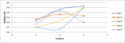
I've annealed for 2.8 sec 3 cases (6 PPC) that were shot many many times.
I've painted them with 750°F tempilag on the neck and body.
I've already measured on those cases the vickers hardness and I know that the hardness on the neck and shoulder is not good, see the graph below. (the light blue lower line shows expected results) (in French, "Attendu"
The measuring points ( from 2 to 5) show a too high level of hardness and as you can see on the photo, the tempilaq melted on this portion too. It melted untill the position 7 on the case.
That means that this temperature is not high enough to get a good annealing.
Soon I'll receive higher temps of tempilaq and I'll conduct new tests. I hope that I'll know the temp applied to the neck portion

2.8 sec annealing and 750°F tempilaq

Attachments

If your looking for the schematic (which should have been on page one of this thread) you can find it on page 110.I always got great results from salt bath annealing, but now I’m considering building the basic GinaErick induction annealer because it seems more convenient to use. I never considered an induction annealer before because I didn’t want to spend a stupid amount of money on it - but obviously that’s not the case here. It looks like a fun project. Thank you for making the design public.
Good luck on your build
Gina
Hello Bruce here’s a question or thought. I just purchased the same timer, and plan on mounting mine under the case front. This is two fold, one for esetics, the other for space saving. I have an idea for using the buttons to program it by say an extended button. Unfortunately I don’t have a 3D printer, so I’m thinking of fashioning an assembly. Any one out there have a similar thought or solution can hit me up to ma this more user friendlyWell spotted Andrew - yes, the resistors are for 48V.
My timer is " PTR4-SP Controller 4-Way Programmable Time Relay 99 step multi-channel " from EBay for about $50. The buttons are beneath the screen (in the black area of the photo) and are a bit small and fiddly but they work. As I have said before, I got this timer because I was not certain that the Sestos timer would accept an input signal from my proximity sensor to start the process. I now believe that it does.

The relay is " Heavy Duty Chassis Mount Relay " - 30A - $7.95 from Jaycar
View attachment 1174257
Both have worked flawlessly for over 6,000 rounds now.
Round1
Gold $$ Contributor
My solution. I posted before I saw you don't have a 3D printer. I have only test fitted it but it does work. I will take some actual photos when I get home.Hello Bruce here’s a question or thought. I just purchased the same timer, and plan on mounting mine under the case front. This is two fold, one for esetics, the other for space saving. I have an idea for using the buttons to program it by say an extended button. Unfortunately I don’t have a 3D printer, so I’m thinking of fashioning an assembly. Any one out there have a similar thought or solution can hit me up to ma this more user friendly


Thank you, Regina. I actually read this entire huge thread and I saved a copy of that schematic. I also noted the change to have a 24volt solenoid with appropriate power supply.If your looking for the schematic (which should have been on page one of this thread) you can find it on page 110.
Good luck on your build
Gina
One issue I did run into is that SainSmart doesn’t make the ZVS annealer board any more - so I am considering a similar ZVS board by Yosoo. If anyone has had a problem with the Yosoo board please let me know!
Last edited:
Patrice,Hello.
Easier to use an induction annealer than the salt bath and pretty much more safe of course.
You'll have to spend a lot of time. Regarding the money, I spent approximately 600.00 euros for everything but mine has an auto feeding system wich is not necessary.
Concerning the quality of annealing with salt bath, AMP tested this system and it appears that it can't reach the hardness level expected. Cases are not fully annealed. You can give a look at this address :
RegardsSalt Bath Annealing - Does It Work? | Learn More | AMP
View the latest articles from AMP Annealing. Get tips and tricks from our R&D. Here we upload articles to provide your the best possible information on innovations in the annealing process.
Patrice
I am very familiar with that AMP article contending Salt Bath Annealing (SBA) doesn’t work. I don’t buy it - reduced effort required to run my SBA annealed brass thru FL sizer on my Rockchucker makes that very obvious.
Other issue I have with AMP is they never addressed the parameters I am concerned with, namely, (1.) it didn’t address SBA neck brittleness/cracking and (2.) it didn’t address SBA consistency of neck tension. I do find the Vickers tests fascinating, but I am only interested in brittleness and neck tension consistency.
I routinely test my neck tension consistency with my K&M arbor press Forcepak, and I see success when I have consistent force measurements to seat all my bullets. But it will be interesting to compare my consistency between SBA and induction.
So big attraction of the induction for me is convenience, and I’m also looking forward to trying something new to me - and pleasure of working a fun project. Have a good one!
Post Edit: my cartridge of choice is 308, and I use Lapua and various sorted military brasses all of which have necks turned to consistent 14thou. I anneal with every loading, I use custom neck-honed (0.3340”) conventional Forster full-length sizer die without expander spindle (headspace bumped by 2thou), I use a separate “21st Century” expander mandrel die, and I use a Wilson seater on my arbor press.
Last edited:
I'm going to kill a myth.
Patrice
This is really good work. However I'd like to see things standardized and controlled a little better. Take, for example, 3 virgin (unfired) pieces of brass of one caliber. Measure these and show us where these points are on the brass (as you did here). We have a baseline for comparison. Shoot these same cases, say, 5 times and measure again with consistency of measurement points. Show the comparison graphically (perhaps you average the cases at each measurement point for these types of comparisons). Now we see how firing work hardens the brass. Then anneal showing the impact to Tempilaq color change. Show us how these cases sat in the work coil. (When I'm annealing I make sure your point 7 or 8 - one shoulder width down the case wall - is in the middle of my work coil even if it means the mouth of the case is poking out the top. To your post #2305 I would probably be saying 'move the cases higher in the work coil and maintain the higher anneal times.) Measure again and present the comparison. For each annealing scenario you will need to show those same cases throughout the virgin->fired->annealed process and their measurements so start with enough cases to allow enough annealing testing. I also think you need a few data points (3 or 4?) around the circumference of the case at each measurement 'point' with these then averaged to average out imperfections in the brass thickness and - importantly - imperfections in the placement of the brass in the centre of the work coil. This would be most relevant on the unturned portions. (I ended up adding inserts in my shelf design to make sure the brass was more accurately centered in the coil.)
(You could do a little testing beforehand to narrow down some of the scenarios you eventually put through the whole test.)
I'm not sure you're heading in the right direction re modifying your work coil. As you are finding, dealing with the neck is much easier than dealing with the shoulder. And you don't want too cook the neck trying to get the shoulder right. (I have pushed it too hard before and the neck brass got so soft that I could squeeze the neck closed between thumb and forefinger.) Ideally we need concentrated application of current at the shoulder/body junction (and relatively fast annealing times). This is where the air-gapped ferrite core work coil comes into its own (and I am not surprised that AMP use this. The work coil in the GinaErick design is not well suited to annealing cartridge brass but it is easy for people to construct. I'm not sure that your proposed modifications to the work coil achieve what you are after but designing work coils is an electronics skill in itself. Maybe you know the induction field and eddy current effects of what you are doing.
One other suggestion. We believe that AMP's Aztec feature monitors current to determine the point when the brass gets too hot (and softens dramatically). Current increases steadily as the brass in the work coil heats but then collapses when it gets too hot. Previously in this thread I have posted a link to work done by one builder which plots this sudden drop in current. This 'destruction of a case' test allows Aztec to determine this point in time for a given case batch. From there they back off 'just enough' with that formula testing via Vickers hardness testing. If you can integrate this current monitoring into your build you will be much closer to determining a method for optimal annealing time that doesn't require you to go back to Vickers testing for each batch of cases you wish to anneal.
Regards
Steve
itchyTF
Gold $$ Contributor
I added inserts for different case sizes and I can adjust the platform that the case sits on in the X, Y and Z direction. Even though the cases are fairly centered by eye I notice when power is on the case moves slightly. It appears that it is self-centering. Don’t know if anyone else has experienced this.(I ended up adding inserts in my shelf design to make sure the brass was more accurately centered in the coil.)
inserts -

My cases self center, but if they are way off line they just self disalign as well. They arent trapped within the coil though and are free floating on a disc within a ferrite core.
Re the amperage that the cases get, my amps are way down at 5 to 7 amps over a time period of 5.4 secs for lapua .308 brass. but I do notice it fluctuates as the case heats 38 V PSU
When using a typical helical coil the amps run up to 8 or 9 for comaparison but thats also at 42 V
Flux concentrator on right
Last edited:
Last edited:
It's quite hard to see the coil in that pic. Can you zoom in to the ferrite and windings? How many turns around the gapped ferrite did you do?
(I'm from Hastings, HB)
@bigfish27 I suspect the air-gapped ferrite core design is better. The bulk of the flux path is around the ferrite and across the gap. So long as the air gap is small versus the cross sectional dimensions of the ferrite there's little loss. There's a little fringing effect (which is likely helpful for our application) and some leakage across the wider gap but the field across the air gap is much more concentrated than in a 'standard' coil design. If you start overlapping coils I think you collapse the induction but I'm not sure.

When dealing with these types of situations once has to be very careful regarding saturation and heating of the ferrite core. This stuff is way above my knowledge level.
Last edited:
Similar threads
- Replies
- 74
- Views
- 47,581
- Replies
- 0
- Views
- 1,592
Upgrades & Donations
This Forum's expenses are primarily paid by member contributions. You can upgrade your Forum membership in seconds. Gold and Silver members get unlimited FREE classifieds for one year. Gold members can upload custom avatars.

Click Upgrade Membership Button ABOVE to get Gold or Silver Status.
You can also donate any amount, large or small, with the button below. Include your Forum Name in the PayPal Notes field.
To DONATE by CHECK, or make a recurring donation, CLICK HERE to learn how.
Click Upgrade Membership Button ABOVE to get Gold or Silver Status.
You can also donate any amount, large or small, with the button below. Include your Forum Name in the PayPal Notes field.
To DONATE by CHECK, or make a recurring donation, CLICK HERE to learn how.