• This Forum is for adults 18 years of age or over. By continuing to use this Forum you are confirming that you are 18 or older. No content shall be viewed by any person under 18 in California.

Induction brass annealer redux

Has anybody tried stainless brake line for the coil?

Nada, three choices would be copper (101 or pure), silver, and gold. Needs to be the best conductor of electricity and heat the budget allows. Stainless is deficient in both electrical and heat conductivity compared to copper. Copper becomes the only choice when price is considered.
 
I thought I would post a couple of pics of my shelf setup. It has been printed using SLS 3D printing technology. I used the same print service that I used for the autofeeder parts. A slightly amended version is currently being printed using the more advanced HP Jet Fusion 4200 printer and it's very innovative technology.

(Click on the thumbnail to view a larger version.)
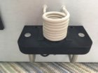
IMG_3448.JPG

It is 15mm thick and the OPB819Z IR switch is embedded in the shelf with the wires passing through holes to the bottom. The main reason to embed the IR switch (it is just push fit) is to not lose the height adjustment (about 8mm) for a smaller case such as .223 Rem. Now the shelf can be moved closer to the bottom of the coil.

Here's a couple of shots of the solenoid setup. The solenoid is simply attached via some rather strong double-sided padded tape I have. It can, with a little effort, be removed and refitted. The trap door shown here is a prototype fashioned by hand from an HDPE chopping board. (Don't tell my wife.) I've also designed a version in 3D software and it is being printed alongside the modified shelf. A tap hole for M2 thread is placed on the underside of the shelf as part of the printed design to be used as the hinge point for the trap door paddle. The link was fashioned by hand out of 1mm aluminium. It is rigidly fixed to the solenoid shaft. Play in the socket where it attaches to the trap door paddle prevents binding. The flat on flat surfaces prevent the solenoid pull rod from rotating.
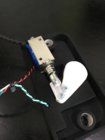
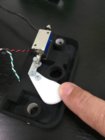
IMG_3449.JPG IMG_3450.JPG

The shelf rides on rails which are merely these cabinet door handles cut to length. I think I purchased the 4" wire pull version (and they cost about $4 for 2). (I note they are currently out of stock but I am sure that is a temporary situation.) An M4 set screw at either end of the shelf holds them in place. Here I very much borrowed from the tidy design of @dabeechman (post 818 on pg 41). Thank you dabeechman.

https://www.ebay.com/itm/Cabinet-Pull-Drawer-Handle-Knob-Satin-Nickel-Swiss-Kelly-Kitchen-Hardware/323038148019?ssPageName=STRK:MEBIDX:IT&_trksid=p2060353.m2749.l2649

http://swisskelly.com/categories/wire-pulls.html

The slightly amended version of the shelf I am having printed corrects the diameter of the holes for the rails (you can see in the pics that I reamed these out 0.5mm) and their placement***, and also increases the drop hole to accommodate 338 Lapua. When I was doing these revisions @BillK55 convinced me to design an insert which would help ensure that a smaller case such as the .223 Rem would drop into the centre of the hole. The insert is merely placed in the hole and aligned so as to not block the IR beam of the switch. It reduces the hole from 15.5mm in diameter to 11.5mm (versus the 9.6mm width of a .223 case). The 55 degree chamfer of the hole mouth is maintained.

Insert pic.jpeg

The parts are fantastic quality. A print run of 2 shelves, 2 inserts and 2 trap door paddles costs about $65 (including $5 for delivery). So in the grand scheme of things it is quite economical for a professionally manufactured product and saves a tremendous amount of hassle figuring out this part of the build. All I have to do is thread the M4 tap holes and the M2 hole for the trap door hinge and the shelf is done.

If anyone is interested in following a similar setup just send me a PM.


*** I have two of the first version, reamed and threaded which I can sell. They work just fine if the rails are spaced off the front of the enclosure by 3mm - the amount of material I placed behind the IR switch. I merely forgot to adjust the hole placement. They have a 14.5mm drop hole and so not big enough for 338 Lapua and, as a result, the insert mentioned won't work with these. Other than that they're rather awesome.
 
Last edited:
I already got schooled for saying that. Yes technically they're inductors, but on that board they're functioning as filters to keep the high frequency (generated by the ZVS) from going back into your main power supply.

They're chokes and prevent high current spikes.
 
So I was playing around with my unit today doing some testing. I noted that when I have 5V out of my rotary switch to fn 7 on the RSP 750 48 PSU my ammeter reads 18A. It's meant to be 15.7A. (Well the test report shows the unit tested was at 99.3% of rated current at 5V.) Bad shunt? Other ideas?

EDIT: I notice there are SMD trim pots on the ammeter board, one marked I-adj and the other V-adj. I wonder if mine was never calibrated to the shunt.
 
Last edited:
Finally got the time to send autofeeder parts out for manufacturing. Hopefully they all fit. This set has the base plate and a disc for the "308 group" of cases (anything in the 12 x 47-52mm range) and a disc for the "223 group" (223 Rem, 6PPC, 6BR etc). I ordered two sets - one for me and one for a friend. The other had discs for 6.5x55 Sw and 300 WM, plus the base. I use Ponoko to cut the designs. These parts are in 4.5mm/0.177" black acrylic. Blue is a cutting line while red is an engraving line. I thought the engraved lines would help with placement of the 'bumpers' on the discs. If anyone wants to tag along with this sort of autofeeder just send me a PM.

EZ Anneal charges $50 for a feeder plate/disc. I didn't pay much more than that for all this. A little countersinking and a coupling on each and they're done.

Autofeeder base plate and discs.jpeg
 
Last edited:
You could probably get away with fewer steps, 7 steps is more than enough in the real world, 4 or 5 would cover everything from 22 hornet to 50 BMG, just set up the resistors on the switch to cover the entire range from 2.1v to 5.0v in even steps.

Attached is a spreadsheet to help calculate PS output for each resistor step and the resistor value needed. These are approximate values as the response is not perfectly linear but in reality they are pretty close, within +/- .1 A .


Ugh I knew I should have searched for something like this. @GrocMax how did you find out the input impedance of fn pin 7 as 6kR? I had looked at the datasheet and seen nothing and presumed it very high. I found out the very hard way that this was wrong by wondering why my rotary switch output voltages were much lower than expected. I had to solve for the real voltage divider 'bottom leg' resistance that fit my data (3.75kR) and then solve for the parallel resistance of 10kR||xkR = 3.75kR.

I have 10 switch positions. I was targeting 3.2V to 5V. Because of the lowish input impedance of pin 7 I have 2 to 5V. I'm now wondering whether to lift the 10kR substantially in order to raise the lower end of the range a little...

(I also have a non-shorting rotary switch but I'm not sure this is a big deal.)
 
Last edited:
BTW people may find it easier to solder the resistors off the poles rather than between the poles, particularly if they have a high position count. Then whichever resistor value is soldered to a particular pole becomes the top resistor in the voltage divider (and the parallel resistance of the bottom resistor, e.g. 10kR, and the input impedance of function pin 7, i.e. 6kR is the lower half of the voltage divider).

IMG_3458.jpg

All the resistors are joined together at the other end in an arc. 5V is attached to the centre pin and both the wire to PSU fn pin 7 and the wire to 10kR (or whatever) to ground are connected anywhere on that outer arc. (Obviously one of the positions will have a straight wire connection to the ring. Using one of the clipped leads is easy.)
 

Attachments

Last edited:
Ok sounds like we got there the same way. More fool me for not leveraging your earlier work. I had assumed when nothing was mentioned in the datasheet that the impedance of the function pin was high enough to not impact things. It wasn't until I changed from a trimpot to a rotary switch that it was obvious the input impedance was very low and causing significant effect. 6kR made all 10 results 'fit' and only then did I go back and find your spreadsheet. I would have expected such a low impedance to have been mentioned in the datasheet. Oh well. Now if I could only figure out why my ammeter is off. I guess I shouldn't expect much from a $6 part sold on eBay. I've ordered another to compare.
 
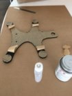
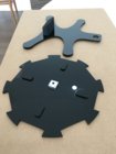
The thread has been quiet for a bit so here's a few pics. A package arrived today with the acrylic parts for my autofeeder.

IMG_3468.JPG

This sheet has the base and feeder discs (a) for .223 Rem, 6mm PPC, 6BR and similar cases and (b) for 308 Win, 6.5 Creedmoor, 6 x 47, 7mm 08 etc cases (anything in the circa 12mm x 47-52mm range).

Solvent welding the 'feet' on the base:

IMG_3469.JPG

Adding the bumpers to the feeder discs:

IMG_3470.JPG

Solvent welding takes a bit of practice. I left the wrapping on while I did it just in case I spilled the solvent. As it was I had a spill on the first one. By the time I had done two bases and 4 feeder discs I had the process down a lot better.

Feeder disc and base with rear pedestal attached:

IMG_3472.JPG
 
Last edited:
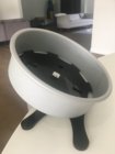
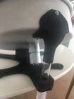
And a few shots of the assembled auto feeder. I still have to figure out how best to cut the drop tube to length (plus I need to increase the size of the aperture in the hopper a little more). The idea is that this sits on top of the annealer with the drop tube extending down into the work coil. The base acrylic has a bit more flex than I thought it would and so I might add a 'foot' at the centre as well. The drop tube is a tight fit in the hole in the base and the clamp may only be necessary if it loosens over time. I'm just glad it all fits.

IMG_3473.JPG IMG_3475.JPG IMG_3477.JPG
 
Thanks. I have tried to make this relatively versatile so others can use it in their builds if they want. Obviously the clear drop tube can be as long as needed. The unit can reach over the front panel of a GinaErik build by up to 5.5cm (a little over 2 1/8") for alignment with a work coil. It has a footprint of 10" wide and up to 8.5" deep (if the drop tube only just overhangs the front panel and so less if extended more). Parts are available from eBay/Amazon etc and the 3D printed or laser cut acrylic parts can be ordered via me. (I would just print/cut the designs and have them ship directly. Not looking to make money out of this, just cover costs. I use Ponoko to cut the acrylic parts and a particular provider from 3dHubs to do the 3D printing. The 3D printing quality via HP's jet fusion technology is awesome and simply not comparable with FDM printing which can't print the drop shoot part anyway.) Some people might want to fashion their own base but I recommend getting the other parts done via these providers. If someone wants to make their own pedestal and clamp to fit I can help with the required design geometry but frankly it isn't costly to have them printed (when compared to the time required to make them). The printed drop shoot is a complex design. I had to model the entire unit in order to get it right.

What work is required to make this?

1. The biggest thing is drilling the motor mounting and rear pedestal holes and cutting the drop aperture in the hopper (cake tin). The motor mounting plate can be used as a stencil for the former once you have the centre of the hopper (which a couple of speed squares will do for you). A step drill bit is needed to drill out the hole for the motor shaft. A hand fret saw or similar and file is needed for the drop aperture. Measuring out the holes for the pedestal isn't hard.

2. The motor mounting plate (a 3mm acrylic disc sitting on the inside of the hopper and used to clamp the motor to the hopper) needs its holes to be countersunk. The motor requires M3 screws and so the countersinking bit ought to be 90 degrees.

3. Each feeder disc has a motor shaft coupling which attaches to the disc via 4x 6-32 screws and the holes in the acrylic disc need countersinking (82 degree).

4. Some bits need to be glued/welded together. I recommend using solvent welding and you can buy this stuff on Amazon

5. The clear drop tube needs to be cut to length

That's it.

What's needed for it to work?

The motor needs a 12V supply. You also need a mechanism for turning the motor off when a case is in the work coil (else it would keep feeding cases). I use an IR switch in my shelf and a control board which, amongst other things, controls the supply of 12V to the feeder motor. There are lots of ways to skin this cat, but if anyone wants to use my control board I have spare PCBs.

Any questions? Just ask.
 
A pic of the whole thing. (I don't have the clamp on there for this shot.) Still a bit of work to be done. Initially I was thinking it would be good to have the clear drop tube go well into the coil like it is now. However I think it might be better to have it only go to the top of the coil else there is a risk the tube doesn't let the case centre properly in the shelf hole.
 

Attachments

  • IMG_3479.jpg
    IMG_3479.jpg
    172.3 KB · Views: 171
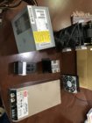
82F2AAE1-BD5D-46AE-BB83-8A48FC59F75C.jpeg My acquired parts so far...
I thought I might expand my horizons a bit by learning PLC programming and integration
 
Last edited:
Can you do a PCB? I can give you my code for the Microchip PIC I am using. Or you can use one of my PCBs. (Adapt the code if you need to.) Otherwise I would go down the Arduino route if I were you.
 
How far down the case body?

This is a little less than the width of the shoulder. 308 Win, 4.8s and circa 14.7A.

IMG_3480.jpg
 
Can you do a PCB? I can give you my code for the Microchip PIC I am using. Or you can use one of my PCBs. (Adapt the code if you need to.) Otherwise I would go down the Arduino route if I were you.
I thought I might try Velocio. What’s better?
My electronic skills are fine but unable to print a board
 
My acquired parts so far
Is that your ZVS board on the right side of the picture? From the looks of those impressive heatsinks I'm guessing your board has 4 MOSFETs? Did it come with the two fans on top, or did you add them? Please tell us about the specs for your ZVS, and maybe post a link of your source. It looks really heavy duty.
 

Upgrades & Donations

This Forum's expenses are primarily paid by member contributions. You can upgrade your Forum membership in seconds. Gold and Silver members get unlimited FREE classifieds for one year. Gold members can upload custom avatars.


Click Upgrade Membership Button ABOVE to get Gold or Silver Status.

You can also donate any amount, large or small, with the button below. Include your Forum Name in the PayPal Notes field.


To DONATE by CHECK, or make a recurring donation, CLICK HERE to learn how.

Forum statistics

Threads
165,242
Messages
2,191,983
Members
78,771
Latest member
AndrewL
Back
Top