• This Forum is for adults 18 years of age or over. By continuing to use this Forum you are confirming that you are 18 or older. No content shall be viewed by any person under 18 in California.

Induction brass annealer redux

Thanks everyone for your input regarding the pc power supply limitations.
I have dropped that idea and will use the two that I hooked up in series for some other project down the road.

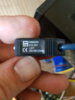
Today my B3S timer arrived so it's starting to itch again LOL
Still waiting for the induction board, volt/amp meter and relay though :(

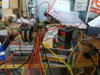
I'm working on a new low cost power supply solution from 2 hacked microwave oven transformers (MOT).
(have more time than money I guess haha.) This should give me more amps and then I'm not limited by overprotection circuits in a PC PSU.

Have removed the secondary windings on one transformer and rewound it with 12ga wire, still need to do the other one.
When I power up the transformer primaries in series then they each run on about 60v input and 12.5v output.
So when I connect the secondaries in series I will have about 24v.
It's AC so I still need to find a rectifier to convert to DC. (ideas for low cost rectifier
solutions are welcome)
Unfortunately I don't have an amp meter so have no idea yet what the current output is.

The annealer will be heavy as h3ll once done....the MOT's alone weigh 9.5 lb each.
I decided on using two mot's with 60v input because running one on 120v will most likely overheat.

That's the update for now, Merry Christmas everyone!

Don't be shy to what output voltaje of the MOT is concerned. Since you are thinking of rewiring the secondary, you should go for 36V which, in my opinion, is the ideal voltage.
The 24V will take you to a very hig Amp demand, which means stronger wiring and contacts.
By the way, if you are thinking of a relay for the induction PCB, make sure it is a double contact switch (DPDT), and also that the contacts are, at least, with a gap of 3mm in the N.O. position. Otherwise you may have a BIG spark at the disconection.

Thanks Jose,

Unfortunately I could not get any more wire on the secondary coil (won't fit) so I can't get it to 36 volt. I could if I rewind with 14 ga wire but that might be too thin.
If I hook up more MOT's in a different configuration I could also get a higher voltage but then the annealer will be even heavier.
I'll probably have to wait until my Volt/amp meter arrives so I can see what the two mot's are putting out at 24v with no load.
Might not be too bad since they both only get half of the power voltage (60v) input.

Thx again.

Are you using bare copper wire for the secondary? If so, make sure none of the turns touch. Depending on whose chart you look at, 14 ga wire can vary but I would think 15 amps would be fine.
 
Are you using bare copper wire for the secondary? If so, make sure none of the turns touch. Depending on whose chart you look at, 14 ga wire can vary but I would think 15 amps would be fine.

Not bare, that would short out.
It's regular romex house wire (solid core, not stranded) that I had laying around.
Stripped the sheating/outside layer off and used one of the insulated wires.
 
'Magnet wire'. Made for coil windings, dead soft with a very thin clear insulation layer on it.

Thanks for your idea. It might be the best wire but it will defeat the purpose of a "budget build", then I might as well buy the $70-100 48v power supply.

Where possible I'm trying to build it with as many components that I have laying around, can get for free (like old microwaves) or can get cheap.
I don't care if it takes some time, for me the build is also fun and a learning experience on the electrical side of things.
 
Here's the schematic for the drop tube mounted reflective IR optical stop switch. Must have a 5v supply.

Why put a "stop" circuit in it? Just leave the timer in "one cycle mode" (single shot mode) All will stop after the last case and will start up again when a new case falls in front of the start sensor.

Gina

OPB716Z_zpsj4fdtlrk.png
 

Because if you don't, cases will drop on top of one another. The Dillon case feeder doesn't always fill every slot with a case, so you need to set timer C long enough to insure a case drops, then STOP the case feed motor so another one doesn't drop, and the trap door is reset to closed. STOP is to terminate Timer C as soon as possible.

I didn't want to change or modify the case feeder at all, so it simply plugs into a 120v outlet on the back of the box that the live leg is controlled by Timer C via a relay. In case you're wondering I've used mini 30A 12v automotive relays many times on sub 1/2 HP AC motors and heater elements with 12v relay coil control, they work just peachy and last.
 
Last edited:
Because if you don't, cases will drop on top of one another. The Dillon case feeder doesn't always fill every slot with a case, so you need to set timer C long enough to insure a case drops, then STOP the case feed motor so another one doesn't drop, and the trap door is reset to closed. STOP is to terminate Timer C as soon as possible.

I didn't want to change or modify the case feeder at all, so it simply plugs into a 120v outlet on the back of the box that the live leg is controlled by Timer C via a relay. In case you're wondering I've used mini 30A 12v automotive relays many times on sub 1/2 HP AC motors and heater elements with 12v relay coil control, they work just peachy and last.

To better understand your set up, what turns on the case feed motor? I know you said timer C. The NO contacts are used for the trap door solenoid, so how are you set up ?

BTW Not having used 12V auto relays, all I can relate to is the problems Jose was having with them.
 
To better understand your set up, what turns on the case feed motor? I know you said timer C. The NO contacts are used for the trap door solenoid, so how are you set up ?

BTW Not having used 12V auto relays, all I can relate to is the problems Jose was having with them.

OK I got !! it with your stop/start circuits. Had to mentally add them in to the system.

Gina
 
I'm using the 12v-24v relay output versions of the timers, since I'm automotive-centric and have lots of 12v DC related supplies at hand.

Here's how its set up in a logic progression-

Timer set to one shot mode.
START switch turns on when case breaks the beam of the optical switch mounted just above the plane of the trap door for 100mS.

Timer A increments to set point, Timer A output operates induction coil.
Timer B increments to set point.
Timer C increments to set point. Timer C is fed 12v (or 0v to 12v PS gnd, doesn't matter its DC can switch either low side or high side of the load) on the common terminal, and the NO terminal is connected to a 12v relay coil to operate the case feed motor, the 12v trap door solenoid (and in my setup the counter input). Timer C set point must be a fairly long set time to allow a case to be picked up by the case feed plate and dropped into the drop tube. Case trips the STOP optical switch for over 100mS at the very top of the drop tube, the case feed motor stops, the trap door closes in time to catch the case. Case drops down into START switch beam and the process starts over. Timer D does not increment because the STOP signal brings it back to square one in one shot mode.

When the counter has reached the set point it holds the STOP signal on, which suspends any further operation until the counter has been reset. If there is no counter set point it just increments up (or down) until you reset PV.
 
Last edited:
I'm using the 12v-24v relay output versions of the timers, since I'm automotive-centric and have lots of 12v DC related supplies at hand.

Here's how its set up in a logic progression-

Timer set to one shot mode.
START switch turns on when case breaks the beam of the optical switch mounted just above the plane of the trap door for 100mS.

Timer A increments to set point, Timer A output operates induction coil.
Timer B increments to set point.
Timer C increments to set point. Timer C is fed 12v on the common terminal, and the NO terminal is connected to a 12v relay coil to operate the case feed motor, the 12v trap door solenoid (and in my setup the counter input). Timer C set point must be a fairly long set time to allow a case to be picked up by the case feed plate and dropped into the drop tube. Case trips the STOP optical switch for over 100mS at the very top of the drop tube, the case feed motor stops, the trap door closes in time to catch the next case. Case drops down into START switch beam and the process starts over. Timer D does not increment because the STOP signal brings it back to square one in one shot mode.

When the counter has reached the set point it holds the STOP signal on, which suspends any further operation until the counter has been reset. If there is no counter set point it just increments up (or down) until you reset PV.

Nice set up... Kind of figured what you were doing.

Looking forward to a video, when you get a chance. Would be kind of neat to see it in operation.

Gina
 
I plan on getting the case feed portion up and running over Christmas vaca, still need a few bits to work out the rest of it to get it all going. I figure a good stress test of the case feed setup is to see if it can count 200 cases in as short a time as possible, say 3-4 minutes and no drops, double stacks, or other errors, see which case feed motor speed (there is a high and a low speed, switched) works best.
 
"fist pumps air", "gives hugs to GrocMax"
Happy as guys got my sensor working and its how i wanted it so a very happy xmas to me

Merry xmas guys and thank you for all your hard work to make mine easier.

will make a small vid later to show it off, but very stoked :)
 

Attachments

  • 20161224_165119.jpg
    20161224_165119.jpg
    408.8 KB · Views: 706
  • 20161224_165202.jpg
    20161224_165202.jpg
    92.3 KB · Views: 656
WOW..... Looks nice. Nicely put together. I know you still have the auto-feed to get going, I'm sure that will be something else. I see the 48VDC PS is 750 watts. I'm sure you will find your case placement for the best transfer of power. BTW what caliber will you be annealing most of the time? With that high current I'm sure your anneal time will be short. With high current your inductor PCB may get really hot, the capacitors, that is. Also with auto-feed you may have a short duty cycle between annealing, for cooling of the PCB.
All new territory....
Great job..
Gina
 
This PS has externally adjustable voltage and current limiter (knobs on front) thus the need for a 5v supply from a LVR. Doing 221FB to 300WM with lots of 223 based and 6BR. Note black knob on bottom, this is the height adjustment, screw jacks the baseplate up and down within the T-slot cut in the front plate. Front plate is a piece of 3mm green Garolite (think 'paper'glass) I had laying around.

Induction PCB has heatsinks glued on the bottom of the board. Fan is shrouded and blows right at 'er.

Went with a 'tennis racket' style trapdoor instead of a direct slide, figured it would be easier with the optical sensor location, plus the spring pre-tension, stroke and leverage are easily set up, those things don't pull worth a darned and are slow when the rod is almost out of the solenoid. Small chain link allows for bind free operation as it swings thru its arc. Brass shoulder screw on pivot and the nylon screw right next to it is the closed position stop.

Oh and the best part- Holley carburetor float soldered to the radiator as the radiator expansion tank, with coolant level sight tube and vent. :D
 
Last edited:
I'm going to start out with a std 1/8" diameter tube straight wound coil, then experiment with a conical asymmetrical optimized coil profile design that I found for OEM case annealing, and then try to form a square tube coil at some point. Square or flattened round tube is supposed to be the ideal, most efficient coil, and the asymmetrical winding (both diameter and coil spacing) is to shape the flux field to the part shape. First step is to cut a coil winder mandrel, left hand thread 6-7 TPI with the correct thread shape for 1/8" tube. Supposedly the most optimized shape for bottleneck cases sort of looks like a short topped hourglass viewed from the side with variable coil spacing, if it makes that much of a difference it means we don't need that much of a power $upply.
 

Upgrades & Donations

This Forum's expenses are primarily paid by member contributions. You can upgrade your Forum membership in seconds. Gold and Silver members get unlimited FREE classifieds for one year. Gold members can upload custom avatars.


Click Upgrade Membership Button ABOVE to get Gold or Silver Status.

You can also donate any amount, large or small, with the button below. Include your Forum Name in the PayPal Notes field.


To DONATE by CHECK, or make a recurring donation, CLICK HERE to learn how.

Forum statistics

Threads
165,405
Messages
2,194,785
Members
78,873
Latest member
jimi123
Back
Top