• This Forum is for adults 18 years of age or over. By continuing to use this Forum you are confirming that you are 18 or older. No content shall be viewed by any person under 18 in California.

Induction brass annealer redux

With regard to what temperature to use. This thread is years old and initially it seems people were happy just getting to somewhere around 700 F, it seems now that may not have been hot enough?

I wonder if anyone who annealed to that temperature had trouble with case splitting or accuracy problems and have you moved on to getting the cases glowing.
 
The metallurgists on here could answer that better but from what I’ve read nothing happens to the grain structure at that low a temperature especially for the amount of time it is exposed.
 
The metallurgists on here could answer that better but from what I’ve read nothing happens to the grain structure at that low a temperature especially for the amount of time it is exposed.
Not exactly, but the part about trying to flash anneal the neck requiring higher than 750F is correct.

We investigate cartridge brass if exposed to higher than 400F. Not to belabor the point, but that is because in thin sections things happened differently that they do in thicker sections like the ones used in standardized metallurgical testing. Most times things were okay, but not always, which meant things do start happening below 750F but not the things we are discussing here.

Brass has some magical properties, and one of them is a gift to home reloaders when it comes to annealing necks. You would spend a lot of money trying to calibrate temperature sensors or hardness values if it were not for a little gift called The Draper point.

The Draper Point is a phenomenon for all metals and almost all solid materials. It is the temperature where the "glow" or spectrum of light emits a particular frequency that we find in almost all metals to be about 798K (977F or 525C) plus or minus just a little. It also just happens to be the temp range for flash annealing cartridge brass.

For a home reloader, in a darkened room when that first faint infrared glow starts, we can safely say we are at about 525C (977F). When the cartridge brass necks are bought to that temperature for just a heartbeat, the hardness value will usually be between 90 - 115 HV.

To keep things simple, if you bring the neck and start of the shoulder junction to a dull glow in a darkened room for a heartbeat and you followed up with hardness testing, you would pass the annealing tests. If you try to get more picky about wanting a tighter spec on hardness, you time that process up or down just a little and you can move the hardness numbers up or down several points.

The heat rate concept is also worth mentioning. We don't want to ramp up so fast that the process is very sensitive to timing or subject to overshooting. We also don't want it so slow that the body gets over 400F.

With gas, the single or double torch method means you can get that glow on something like a 223 case in about 6 or 7 seconds for just a beat and be fine. With too much RF power in an induction annealer, you have to be mindful of going too fast and making the timing very critical or overshooting. Keeping that heat rate at about 7 seconds for a 223 or say 9 seconds for a 30-06, would make it easy to keep the process under control with respect to enough heat for annealing the necks but also not so slow that you over heat the body.

Using 400F Tempilaq in a stripe down the length of the body is a good way to observe the heat rate issue. As long as the Tempilaq stripe isn't showing that temp very far below the body-shoulder junction, then you are doing fine with respect to process control. You don't want to see that Tempilaq turning half way down the body or you are letting the process take too long.

So, Draper point (dull glow in a dark room) for the whole neck into the shoulder junction for just a beat, then use 400F to protect the case body. Just keep it simple and don't try to go too fast or too slow. YMMV
 
Re; The Draper Poin
The heat rate concept is also worth mentioning. We don't want to ramp up so fast that the process is very sensitive to timing or subject to overshooting. We also don't want it so slow that the body gets over 400F.
You are
So, Draper point (dull glow in a dark room) for the whole neck into the shoulder junction for just a beat, then use 400F to protect the case body. Just keep it simple and don't try to go too fast or too slow.
You are absolutely correct. Let me define the beat;
Re: Post #2410
Quoting VenatusDominus

"This is easy to plug into Excel and if you pick 810.9 K (1000 F) for your target temp you will anneal in 1.88 seconds. Note that brass starts to glow between 950 F and 1050 F. Using 900 F changes the required time to 16.1 seconds.

B=1.38065x10^-23 (Boltzmann constant)
E=0.327x10^-18 (constant for the material, in this case brass)
T1 in Kelvin = 644 (700 F)
t1 in sec = 3600 (1hour)
T2 in Kelvin = target temp
t2 in sec = time to anneal
t2=t1*exp^(-E/B*(1/T1 - 1/T2)) "


My latest built employs discrete closed loop control system (every 10 mill seconds, 1000F +/- 1% temperature check cycle, switching the power to ZVS On/Off) . It maintains the temperature for 5 more seconds. The full anneal (100-120 hardness - my estimate loocking to verify it), after the "beat" does not change.

A member in this forum uses super sophisticated closed loop based on PID algorithm.

Rate of heat: The time for a same lot brass, reaching 1000F varies (+/- 5%). Most likely the amount of material (turned) in the neck is different. The average time for .284 Winchester Bras is 2.8 sec, 6mm Dasher under 2 sec.

My inductor is ferrit core (Fluxeon). The current to the ZVS is constant 13.5 amps out of 750 watts Mean Well PS.
 
Blew another ZVS board after a year or so and lots of cases. This was the bigger 1800 watt version. I don't know how many blown components at this point but I thought this board with a Meanwell PS and Crydom SSR had it licked. Got another from Amazon and something popped as soon as it started annealing and of course doesn't work. Any way to find out what's blown and replace it or a reliable ZVS board?
I think the new boards have inferior fake MOSFETs on, I blew 2 boards in a row. Started up fine, mine idles at about 10A, did that without a problem. As soon as I started annealing the board blew. Tried another one and this time kept an eye on the current and slowly lowered the case into the coil, at 15A the board blew.

The boards are easy to diagnose and fix and. This guy show exactly how to diagnose the boards: https://spaco.org/Blacksmithing/ZVS...oltZVSInductionHeaterTroubleshootingGuide.htm

On my boards, the first one blew one MOSFET and both 12V zeners. The second board also blew one of the MOSFETs. The MOSFET's that did not blow, measures correctly 5.1k ohm when in circuit, but out of circuit measuring from D to S, gives me 3.5MegaOhm instead of the expected 7.26Megaohm, hence the reason I think they are inferior.

I am repairing mine, but are going to use some better components. For the MOSFET's I am going to use IRFP4668's and I am replacing the 1Watt 12V zeners with 2Watt 12V zeners. These MOSFET's are quite a bit more expensive but can handle more than double the current and have a on resistance of 1/4 of the IRFP260N's so should heat up a lot less. So driving the board at the same power, it should be almost impossible to have it fail.
Thx for the link. I got another and it ran for 1 second on blew.
 
Thx for the link. I got another and it ran for 1 second on blew.
So, I replaced the MOSFET's and Zener diodes on the first faulty unit and it is working 100% now. I also added thermal paste to the back of the MOSFET's while they were removed. I could not get hold of the higher current MOSFET's so just bought IRFP260N's from a reputable supplier in my country.
 
Last edited:
You are absolutely correct. Let me define the beat;
Re: Post #2410
Quoting VenatusDominus

"This is easy to plug into Excel and if you pick 810.9 K (1000 F) for your target temp you will anneal in 1.88 seconds. Note that brass starts to glow between 950 F and 1050 F. Using 900 F changes the required time to 16.1 seconds.

B=1.38065x10^-23 (Boltzmann constant)
E=0.327x10^-18 (constant for the material, in this case brass)
T1 in Kelvin = 644 (700 F)
t1 in sec = 3600 (1hour)
T2 in Kelvin = target temp
t2 in sec = time to anneal
t2=t1*exp^(-E/B*(1/T1 - 1/T2)) "


My latest built employs discrete closed loop control system (every 10 mill seconds, 1000F +/- 1% temperature check cycle, switching the power to ZVS On/Off) . It maintains the temperature for 5 more seconds. The full anneal (100-120 hardness - my estimate loocking to verify it), after the "beat" does not change.

A member in this forum uses super sophisticated closed loop based on PID algorithm.

Rate of heat: The time for a same lot brass, reaching 1000F varies (+/- 5%). Most likely the amount of material (turned) in the neck is different. The average time for .284 Winchester Bras is 2.8 sec, 6mm Dasher under 2 sec.

My inductor is ferrit core (Fluxeon). The current to the ZVS is constant 13.5 amps out of 750 watts Mean Well PS.
I made a web-based calculator using the above formula, you can enter the temperature and it calculates the time required. https://amev2.github.io/docs/resources#anneal-time-calculator
 
I'm such a doofus...I was all ready to post a question about why does it take longer to get to a lower temperature, then I realized the the calculator gives you the time you need to be at that temperature to get the anneal that the formula is designed to produce.

Which is useful if you can heat your brass to the desired temperature and hold it there...which most of our machines cannot do. Some of the brighter among us have made this possible with software and rapid on-off cycling of the ZVS board, but the majority of us just heat up the brass until we stop, adjust the time until we're satisfied with the result, and take what that gives us.
You are correct that most cannot control the temperature. What the calculator does show you is that for the short amount of time we have it at (or slightly above) the required temperature, the time required becomes exponentially longer if you do not reach a proper temperature. What Reese on the range, who demonstrated the formula, says for example at a specific temperature, you do not have to keep it at that temperature for the time calculated by the formula, as you will most likely go over that temperature and when you remove power, the case will stay above that temperature for a little while longer anyway.
 
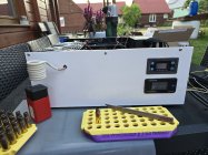
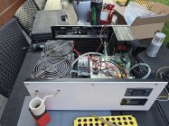
After going through almost the entire thread and gathering components I have built a working prototype of my machine. Still need to sort out this cluster of wires, arrange them nicely and I need to design/3dprint a casing shelf/holder mounted under the coil with buil in trap door
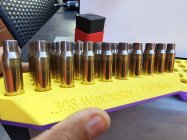
Used ZVS 2400w board, power supply 1200W 25A -time taken to anneal 308win l 3.7sec - I am considering using a 2 layer coil (the idea is to reduce the height of the coil), but from what I have read this may increase the time taken to annealing ?
For now, this is a project in progress, and over time it will surely evolve to automate the whole process
20240717_103953.jpg20240717_104005.jpg20240717_104123.jpg20240718_195334.jpg20240718_195337.jpg20240718_194804.jpg
 
Hope that’s not a made in China SSR.
I honestly can't tell if this is an original Fotek made in taiwan or a Chinese fake. I bought it locally, I have had good experiences with this brand in the past, but with today's counterfeiting of everything, it's hard to be sure
 
Looking good CadetC!

Just to let you know - From my experience, 3D printed shell holders (PETG), have tendency to melt. All of my shell holders are machined from aluminum and/or from high resistant plastic material.
 
I think the new boards have inferior fake MOSFETs...

This is very possible. The chineez are renowned for fake electronics, poor ethics, and fraud in general. Open the dead FETs and if the silicon is the size of a grain of sand then it was clearly a fake. There is a lot of info online on ways to potentially identify (visually) re-labeled, salvaged, sub-standard, etc. parts. They are reading this stuff too though. It seems that the best approach is to expect problems (make sure you can get a refund/return before ordering), test the components yourself and be ready to return them. It's not too difficult to measure the Rds on a FET. Many simple component testers can do this. A very small gate charge is another sign of a tiny transistor disguised in a big package.
 
I did open one of the SSRs that failed in my build. The actual silicon gate material was tiny compared to the package and it appeared to have some added plastic at each end to make up weight. Being in the Electronics industry I had some dead IGBT from some UPS's they were totally different built with steel backing inside to dissipate heat and completely molded unlike a box with a lid on it.
 

Upgrades & Donations

This Forum's expenses are primarily paid by member contributions. You can upgrade your Forum membership in seconds. Gold and Silver members get unlimited FREE classifieds for one year. Gold members can upload custom avatars.


Click Upgrade Membership Button ABOVE to get Gold or Silver Status.

You can also donate any amount, large or small, with the button below. Include your Forum Name in the PayPal Notes field.


To DONATE by CHECK, or make a recurring donation, CLICK HERE to learn how.

Forum statistics

Threads
165,148
Messages
2,190,728
Members
78,728
Latest member
Zackeryrifleman
Back
Top