• This Forum is for adults 18 years of age or over. By continuing to use this Forum you are confirming that you are 18 or older. No content shall be viewed by any person under 18 in California.

Induction brass annealer redux

I would bet that there are multiple anneals during the manufacturing process.
Nice work but so far removed from the original and way more complicated than needed for just about everyone else. Perhaps it deserves it own thread. I am concerned it would put people off attempting to make one of the basic units.
Its a lot of added complexity. Also requires a fair bit more technical knowledge, if you read through the questions that builders have asked just trying to get the basic unit working think if these people could grasp the technicalities that your unit has.

I am not knocking it in any way quite the opposite I think it is a great advancement. I just want to see everyone have the opportunity to get a working unit up and going.
 
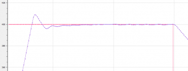
First attempt at a closed-loop PID control of induction annealing temperature using industrial pyrometer. Setpoint is 400°C (approx 750°F). Once settled the temperature is held to within +/- 0.5°C (approx +/- 1°F).


2023-11-25_070622.png
 
Time scale?

The width of the setpoint step is about 9s 11s [Correction]. First crossing of the setpoint occurs in about 3.3s. Horz axis shows sample count, with samples at 50ms interval.

This is not the final coil, so I expect faster rise time with a better matched coil, and with that in mind I haven't spent too much time tuning in its current configuration.

2023-11-26_132204.png
 
Last edited:
Hello!
We have some type of control circuit for NEMA 17 case Feeder?
Some type of stand alone Arduino circuit?

Anyone had some info or TIPS for this application?

Thanks
 
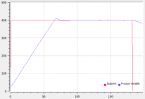
First attempt at a closed-loop PID control of induction annealing temperature using industrial pyrometer. Setpoint is 400°C (approx 750°F). Once settled the temperature is held to within +/- 0.5°C (approx +/- 1°F).


View attachment 1496322
The width of the setpoint step is about 11s. First crossing of the setpoint occurs in about 3.3s. Horz axis shows sample count, with samples at 50ms interval.

This is not the final coil, so I expect faster rise time with a better matched coil, and with that in mind I haven't spent too much time tuning in its current configuration.

View attachment 1496611
Typical Closed Loop performance - great. Could you provide some electrical circuits details and hardware arrangements?

Re - The initial 750 F for 3.3 sec (may be more) - You are correct about the efficiency of the coil. What was the case? How do you determine the time to stop annealing?
In mine built the crossing of the set point (1000F) is around 2 sec. Then the process continues to a total of 5 sec (I use ferrit based inductor ).

Re - 50 ms sample - Is it the limit of the presented system?
Mine sampling limitation is determined by the SSR. The algorithm samples every 10 ms for a deviation of +/- 1% at 1000F.
 
Could you provide some electrical circuits details and hardware arrangements?

It's just a suitable MOSFET, plus a zenner diode for each HEXFET on the oscillator, as described by various others here previously.

What was the case?

.308 Win.

How do you determine the time to stop annealing?

Hardness testing.

Re - 50 ms sample - Is it the limit of the presented system?

No. I guess the limitation would be temperature feedback, which arrives every 1ms. The control loop and output stage could probably keep up with that even on the current (slow) hardware, if it was desirable.
 
Last edited:
rox,

I assume that you are using separate PID controller or may be Arduino based PID algorithm or something else. How do you interface the MOSFTs?

Since you mention hardness test, I wonder if you have any reasonable testing sources? I am dying to check my brass.

Excuse my curiosity, but I would like to see how do you physically monitor the temperature of the brass neck. My flame sensor is an inch from the neck and protected from outside light interference.

Thanks
 
I assume that you are using separate PID controller or may be Arduino based PID algorithm or something else. How do you interface the MOSFTs?

PID is implemented in Arduino code. Arduino output switches the MOSFET, which turns off the HEXFETS via zenner diodes.

Since you mention hardness test, I wonder if you have any reasonable testing sources? I am dying to check my brass.

I use a Webster hardness tester.

Excuse my curiosity, but I would like to see how do you physically monitor the temperature of the brass neck. My flame sensor is an inch from the neck and protected from outside light interference.

Similar. The pyrometer head is about 1" from the case mouth. There's a photo of the test setup a couple of pages back.
 
Thumbs up - a new sophistication (PID decision making) addition to our annealing "machines". Good luck assembling your testing set up. Keep us posted.
 
PID is implemented in Arduino code. Arduino output switches the MOSFET, which turns off the HEXFETS via zenner diodes.


I use a Webster hardness tester.


Similar. The pyrometer head is about 1" from the case mouth. There's a photo of the test setup a couple of pages back.
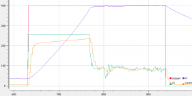
I am assuming that the adrino has a PWM output that is driven by the PID loop output. I would be interrested in seeing the PID output. I am assuming large proportional contribution that will drive the output fully on at the start and collapse to nothing at the first set point crossing. I would also assume that the holding output being the Integral would be a value that at a steady state would keep the case at set point for an extended period of time. This would be a number that would be equal to the heat losses of the case. Then I also assume that the time at setpoint would be fixed for each different case. Just wondring.
 
Really nice work. I like changing the setpoint at the end of the cycle and letting the proportional turn it off. Ineed to read some some but it looks like the board or coil warm up as shown in the ramp up of the current. Few people will understand the effort you put in this control function. Nice job thank you
 
View attachment 1485658

nsussf,
Not to open a can of worms or anything, but here is my offering

Simplest set up (in my opinion)

- adequately large power supply to power ZVS board (and only ZVS board) through large relay.

- large capacity relay (I like the DPDT double pole relay because it connects and disconnects both positive and negative power to ZVS simultaneously). The one I use has a relay switching capacity of 30A of 250VAC or 28VDC, but I've never had an issue switching the 48V/22A I use to power my ZVS.

- separate 12VDC power supply to control the large relay through the small relay on the timer board, any cooling fans and the coolant pump, and any other low voltage components you have.

- a simple timer board that will run on 12VDC and has at least a 0.1 second resolution for the timer annealing cycle and a relay to control the large relay.

This setup will let you run the process entirely manually, with the exception of the timer controling the ZVS run time to a 0.1 second resolution.

- Drop case in coil
- press start
- remove case when anneal complete
- repeat


I think the timer linked below will allow (with the correct programming) you to start it, then it will close its relay in order to anneal for the programmed time, then the relay will open and the anneal will stop, the timer will run for a programmed delay time, and then repeat the entire cycle over and over until stopped.
Again, this is my understanding from looking at the pictures on Amazon, but you should do you own research to confirm.

For example: (on program P7, I think)

-press start (Trigger)

-anneal for (T1,-0) 3.7 seconds (or whatever you program)

-delay for (T2,-1) 15 seconds to allow for case removal/replacement and help control component overheating (longer or shorter time depending on how hot you want your annealer to run)

-automatically start over (C-,00)

--------------------------------------------

Some EXAMPLES of components from Amazon

Large power supply


Small power supply


ZVS Board


Timer module


Large DPDT relay


Coolant Pump/Reservoir


About $175 total plus any switches, copper tubing, wire, etc you might need...
 
hdmunger,

Sorry about my late reply to your updated version of the annealer! I like your improvements! Hopefully I can get this thing put together with my limited understanding of electronics and wiring! Thank you so much for your input! Will probably be in touch from time to time…‍
 
nsussf,
ask away...I check back every few days, and there are lots of people here that can answer any of your questions just as well (if not better).
 

Upgrades & Donations

This Forum's expenses are primarily paid by member contributions. You can upgrade your Forum membership in seconds. Gold and Silver members get unlimited FREE classifieds for one year. Gold members can upload custom avatars.


Click Upgrade Membership Button ABOVE to get Gold or Silver Status.

You can also donate any amount, large or small, with the button below. Include your Forum Name in the PayPal Notes field.


To DONATE by CHECK, or make a recurring donation, CLICK HERE to learn how.

Forum statistics

Threads
165,841
Messages
2,204,021
Members
79,148
Latest member
tsteinmetz
Back
Top