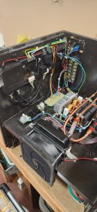
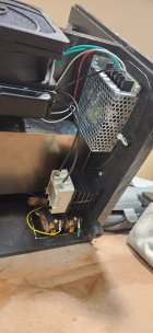
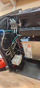
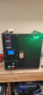
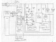
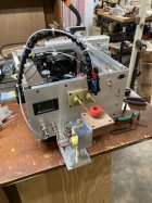
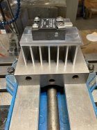
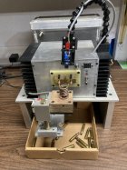
I have an induction annealer I want to sell that I made years ago using the info on this site....all that needs to be completed is the solenoid mechanism to drop the brass. I have two solenoids for this...the mech just needs to be finished. It is working as pictured and was programmed using a plc as I recall ...program was posted here ...I made this to use with my dillon press and it turns on and off the outlet at the bottom. Make me a reasonable offer.

Induction brass annealer redux
- Thread starter Gina1
- Start date


Upgrades & Donations
This Forum's expenses are primarily paid by member contributions. You can upgrade your Forum membership in seconds. Gold and Silver members get unlimited FREE classifieds for one year. Gold members can upload custom avatars.

Click Upgrade Membership Button ABOVE to get Gold or Silver Status.
You can also donate any amount, large or small, with the button below. Include your Forum Name in the PayPal Notes field.
To DONATE by CHECK, or make a recurring donation, CLICK HERE to learn how.
Click Upgrade Membership Button ABOVE to get Gold or Silver Status.
You can also donate any amount, large or small, with the button below. Include your Forum Name in the PayPal Notes field.
To DONATE by CHECK, or make a recurring donation, CLICK HERE to learn how.