• This Forum is for adults 18 years of age or over. By continuing to use this Forum you are confirming that you are 18 or older. No content shall be viewed by any person under 18 in California.

Induction brass annealer redux

I built the annealer in the photo for a friend. Mine is older but similar. Picture attached.

Originally the coolant tank was way too big so I cut it down. It’s still larger than necessary. I didn’t know how big it should have been so I overdid it.
Anneal time can be determined by either push wheel switches (9.99 sec max) or the flame sensor.

Hello,
Can you explain how the trap door and sensor (for brass presence or heat?) work and are made?

My project are all analogic apart the 2 timer.
 
I believe it has been mentioned by a few people in this thread. I’m surprised the coil doesn’t get hot with repeated use. As far as I know all the GinaErik versions (and mine) had hot coils without cooling.
On myne I had used a bare copper wire, about 3mm, and this are very hot when used.
 
Hello !
Sorry for the delay, thanks for the Infos.
If I need plans for brass detector can you send me and explain how make them?

Thanks
 
Hello !
Sorry for the delay, thanks for the Infos.
If I need plans for brass detector can you send me and explain how make them?

Thanks
If you are interested in a flame sensor to detect when your case is annealed, my solution is discussed starting with post #2765 (page 139). It uses Arduino style parts, but without the need for an Arduino...totally analog compatible...just need a 5V power supply.
 
If you are interested in a flame sensor to detect when your case is annealed, my solution is discussed starting with post #2765 (page 139). It uses Arduino style parts, but without the need for an Arduino...totally analog compatible...just need a 5V power supply.
Good!
I read your posts!

Existing one sistem that reveal if the case are on the position inside the coil for starting the annealing?

Thanks
 
Good!
I read your posts!

Existing one sistem that reveal if the case are on the position inside the coil for starting the annealing?

Thanks
I can not help you with that. My annealer detects when a case is fed down from a case feeder and then assumes that case reached the coil. After that, it only relies on the timer for when to start the next cycle.
 
This is the original schematic (so very long ago). Many changes have taken place. I hope this will be a starting point for you. Read the posts in the tread to get ab idea on how to improve on the design. ie replace the 110 volt AC fans with 12 volt DC fans, etc.
Good luck
Gina1
Hi Gina,

Without having to read through the 170+ threads I would like to stay within the confines of your original design as I have no need for a fully automated annealer. I would only be doing a hundred or so cases at a time so won’t mind manually feeding the cases. Further, I am not a high tech redneck especially in the field of electronics! So that leads to my question, what if anything would you change/update on the original annealer design keeping it in mind that I would be staying with the manual feed? What would that schematic look like today if you were to update the design from the original?

Thanks!

SPE
My opinion - you should still use a timer. Induction annealing is fairly fast so errors in timing can mean a lot in the result. You don’t need auto feed but should still use a timer.
Press a button to start, timer runs out, replace case, press button. Etc.
 
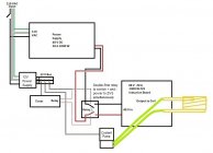
Timer and Relay simplest diagram.jpg

nsussf,
Not to open a can of worms or anything, but here is my offering

Simplest set up (in my opinion)

- adequately large power supply to power ZVS board (and only ZVS board) through large relay.

- large capacity relay (I like the DPDT double pole relay because it connects and disconnects both positive and negative power to ZVS simultaneously). The one I use has a relay switching capacity of 30A of 250VAC or 28VDC, but I've never had an issue switching the 48V/22A I use to power my ZVS.

- separate 12VDC power supply to control the large relay through the small relay on the timer board, any cooling fans and the coolant pump, and any other low voltage components you have.

- a simple timer board that will run on 12VDC and has at least a 0.1 second resolution for the timer annealing cycle and a relay to control the large relay.

This setup will let you run the process entirely manually, with the exception of the timer controling the ZVS run time to a 0.1 second resolution.

- Drop case in coil
- press start
- remove case when anneal complete
- repeat


I think the timer linked below will allow (with the correct programming) you to start it, then it will close its relay in order to anneal for the programmed time, then the relay will open and the anneal will stop, the timer will run for a programmed delay time, and then repeat the entire cycle over and over until stopped.
Again, this is my understanding from looking at the pictures on Amazon, but you should do you own research to confirm.

For example: (on program P7, I think)

-press start (Trigger)

-anneal for (T1,-0) 3.7 seconds (or whatever you program)

-delay for (T2,-1) 15 seconds to allow for case removal/replacement and help control component overheating (longer or shorter time depending on how hot you want your annealer to run)

-automatically start over (C-,00)

--------------------------------------------

Some EXAMPLES of components from Amazon

Large power supply


Small power supply


ZVS Board


Timer module


Large DPDT relay


Coolant Pump/Reservoir


About $175 total plus any switches, copper tubing, wire, etc you might need...
 
You keep saying that, and I keep thinking "what the hell is he talking about?"...

Some pics or diagrams or something might go a long ways towards an electronics dumbass (me) understanding your assertion...
 
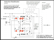
It was covered way back in post #2,946 and before. The standard ZVS board has two big fat solid state switches on it (HEXFETs) Q1 and Q2. If these are turned off the board stops. (It's how the board works in the first place!) You turn them off by grounding their gates. Easy access points to the HEXFET gates are circled in red. If you switch the power supply on and off you are switching a LOT of current and if you are using a solid state relay you have to manage the heat dissipation associated with the Rds(On) of the SSR. In contrast, if the gates of Q1 and Q2 are grounded then a mere 48/470*2 = 0.2 amps of current flows through the 'switch' managing these. A tiny little SMD FET can deal with this let alone a timer module with physical relays.

1697812425329.png
 
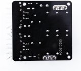
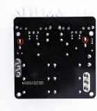
Did you look at the photo in the link I posted? I suspect not.
It's pretty easy to identify the resistors and which side of them you need to tap into based on the points marked in the circuit diagram. I chose to use the R1/R2 through-hole resistor solder pads but equally you could use the one for resistors R3/R4 or the zener diodes D1/D2 or simply the gate pin on the FETs themselves. So a choice of 4 points for each side.
(Hint: rotate the image at the link I provided anti clockwise 90 degrees and then compare with yours. Or rotate yours 90 degrees clockwise and then compare.)
 
Last edited:

Upgrades & Donations

This Forum's expenses are primarily paid by member contributions. You can upgrade your Forum membership in seconds. Gold and Silver members get unlimited FREE classifieds for one year. Gold members can upload custom avatars.


Click Upgrade Membership Button ABOVE to get Gold or Silver Status.

You can also donate any amount, large or small, with the button below. Include your Forum Name in the PayPal Notes field.


To DONATE by CHECK, or make a recurring donation, CLICK HERE to learn how.

Forum statistics

Threads
165,788
Messages
2,203,419
Members
79,110
Latest member
miles813
Back
Top