• This Forum is for adults 18 years of age or over. By continuing to use this Forum you are confirming that you are 18 or older. No content shall be viewed by any person under 18 in California.

Induction brass annealer redux

Hi everyone - will the Mean Well LRS-600-48 power supply work? There doesn't appear to be much difference in the spec sheet from the SE-600-48. The LRS is almost half the cost. I attached both spec sheets.

Either one will work fine for what you are using it for.

Sometimes the difference in price is driven by where the thing is assembled. Meanwell has manufacturing in different parts of Asia.

Also the quality of the components used can differ across product lines.
 
It will also automatically detect and recover lost steps if the feeder gets wedged picking up a case and misses a few.

Also occasionally (2 or 3 in 100) a case will get hung up in the coil and I'll have to poke it with a screwdriver to get it to settle on the trap door.
I like your design approach for the feeder. Can you provide some details for jam recovery algorithm?

Also, proximity sensor is fine, provided that it can distinguish properly seating case in the pilot from a stuck case. I've been thinking of using two very fine electrodes shortened by a properly seating case itself. If you are interested with this approach, I am sure you'll find a way to assemble the electrodes and share it.
 
The step loss recovery is actually fairly simple. I'll start by explaining the normal operation.

The first thing the machine does when it's started is home the drum axis by rotating slowly until it picks up a case and that case asserts the feeder home sensor.

The feeder home sensor is in a specific place so that a case waiting to be dropped asserts it, but it can only be de-asserted by the case actually falling into the funnel.

When a case is called for by the heater, the feeder checks to see that the sensor is asserted. If it is it watches to see that it de-asserts after the drum has rotated a bit, indicated that the case has in fact dropped out of the feeder.

If the feeder home sensor is not asserted at the time the case is called for two things can happen:
- The drum rotates 180 degrees and never sees the sensor assert -> This means that a case wasn't picked up by the drum in the first place and it tries again.
- The drum rotates 180 degrees and at some point in that rotation the sensor asserts as the case passes by and de-asserts as it drops. -> This is an indication that some steps were lost, so the feeder immediately homes itself with the next case.

Since there is also a sensor on the heater trap door we can make some more inferences:
- If the feeder sensor de-asserts (a case drops) but the heater sensor is currently asserted (a case is sitting on the trapdoor still) then a double feed has occurred.
- If the feeder sensor de-asserts (a case drops) and after some amount of time the heater sensor does not assert then the case must be stuck somewhere in the coil or on the case pilot.

Both of these cases halt the machine before the heater turns on and manual intervention is required to clear it.

I've found that with this design geometry the case is not able to assert the heater sensor unless it is properly standing vertically on the trap door so I don't plan to try any alternatives.

Augi
 
Hello, very very interesting post.
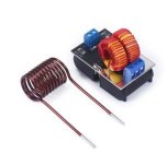
I found this very small 12/24 volts 1000w induction heater on Aliexpress.
Do you think that's enough to try annealing 308 cases?
I've seen you can turn a screwdriver fiery red.
There are also more powerful models like the one in the original post but I would try starting from the bottom.
I don't know if I can put the links of this and of the various models I've found.
 

Attachments

  • EDAA8E24-F586-4890-B880-7C01027BC2F7.jpeg
    EDAA8E24-F586-4890-B880-7C01027BC2F7.jpeg
    40.4 KB · Views: 24
  • 5BCE9011-E80A-4099-939C-35BB6C7A3C9E.jpeg
    5BCE9011-E80A-4099-939C-35BB6C7A3C9E.jpeg
    138.1 KB · Views: 23
Last edited:
I built a simpler modified version of the genaric a couple of years ago. I don't anneal tons of cases, so I've probably only ran 500 or so cases through it. It was working great and all of a sudden quit working. I was hoping some of you electronics Jedis could help me troubleshoot it.

All my parts are from Amazon.... So yes it could just be a poor quality part.

600w 36v 16.6A PSU, set at 33.4V
1000w zvs board
Coil is internally cooled with liquid pump.

This is going to a voltage converter to drop to 12V. My 12V supplies fans, cooling pump, and the timer trigger relay. The 33.4V goes to a voltage/power/ammeter and the ZVS. The timer relay works on 12V and it sends a 12V signal to a 60v 40a SSR. The SSR relays the 33.4V to the ZVS.

When I turn on the main power, it seems functional. My PSU measures 33.4V. the SSR and timer relay are still good ... I disconnected the wires from the ZVS leads and checked the voltage while triggering the timer relay. The timer counts down when triggered and closes the circuit of the SSR correctly, with the load wires measuring 33.4v.

When I have it all connected for use and hit the trigger without any brass in the coil, my timer relay just flashes p1.1 (the mode of the timer relay) instead of counting down, and the SSR contact indicator light only flashes briefly... The timer output voltage when this happens is just a voltage bump rather than the 4.7 seconds of 12v it should be supplying to the SSR. It's almost as if the momentary voltage that is supplied to the ZVS bounces back or something and causes an issue with the timer relay.

When disconnecting the wires from the ZVS and checking for resistance and continuity across the leads of the ZVS board, I get continuity and maybe 0.3-0.4 ohms. Should this have continuity and so little resistance? After searching the web, I think the the ZVS DC terminals should show a good amount of resistance, potentially on the order of 5-5.5k ohms. But it is almost zero on mine.

My coils are not touching each other at all. Last time I used it it seemed to work just fine. I can't find any physical damage on the ZVS board components.

I think it's either the ZVS or PSU, but I can't see why it would be the PSU if that powers everything and measures the voltage it's always been set to. It seems to me that it is likely the ZVS board.

Thoughts?
 
Last edited:
I should step back and let folks who have played with these specific parts give advice, but till then I agree the thing to do is divide the issues between the major parts, the power supply, relay, and ZVS board.

Do you have any other power supply you can use to test the ZVS board?

Sometimes, a power supply puts out voltage when it isn't under any load and then fails to supply power when the load comes on. So, if you can at least split the problem between them while bypassing the power supply you can get somewhere.

The history on the ZVS boards isn't stellar so everything is on the table as far as risk. Hope you find it. Good Luck.

I unfortunately don't have another power supply or any other DC source that could power the ZVS
 
Unfortunately, the ZVS boards I've gotten lately (even from Amazon) have failed shortly after powering up.
And this is replacing them in a unit that had ben trouble free for 5 years. (finally got one that worked)
Gina
 
Unfortunately, the ZVS boards I've gotten lately (even from Amazon) have failed shortly after powering up.
And this is replacing them in a unit that had ben trouble free for 5 years. (finally got one that worked)
Gina

Darn. Is there any high quality ZVS boards for sale anywhere else?
 
Hot tip, if you buy the ZVS boards you can make up yourself, you can swap out the mosfets for better quality ones.
Hot tip #2 for the LED that turns on when the ZVS board is running you can solder a longer lead on and bring that out on the front of the control panel.... that way if you get a runaway board ( relay failed shut) you can see that the ZVS isnt truning off.
 
I’ve blown 3 Zvs boards and a power supply. I’ve had better luck with the 1800 watt one. It’s got two fans and seems a little better built but no guarantees

1800W ZVS Induction Heater Induction Heating Board Module Tesla Coil 12-48V Low Voltage DC Power Supply with a Maximum Current of 40A, Flyback Driver Heater https://a.co/d/gQs5CZn
 
Use the blacksmith site for fault finding tips and walk through to fix the board replace any failed component with a quality one and perhaps a higher spec one. I would put money on your SSR being the initial cause of the fault replace it with a relay until your sure of everything else is in good long term working order then you can replace the relay with the SSR and see if faults re occur.
 
Use the blacksmith site for fault finding tips and walk through to fix the board replace any failed component with a quality one and perhaps a higher spec one. I would put money on your SSR being the initial cause of the fault replace it with a relay until your sure of everything else is in good long term working order then you can replace the relay with the SSR and see if faults re occur.

I ended up swapping out the ZVS board because I was pretty confident that is what failed and I don't have experience soldering components onto boards. I figure it would give me time to troubleshoot the nonfunctioning board and still anneal brass.

Measured resistance across the DC contacts and it was about 5.25 kohms!

Installed the new board, and it runs just like it had before.

How exactly would the SSR have caused the board to go bad? I thought they were supposed to work well in this application as long as it's voltage was rated correctly
 
The SSR market can have some junky ones that are notorious for being unreliable.

The SSR isn't hard to troubleshoot for hard failures, but can be tricky when it comes to soft failures or decay.

The ZVS boards can be a real disappointment too, so unless someone is willing to either troubleshoot and repair, or carry a spare, this kind of project can be frustrating.

Glad to hear you got it going again.
 
Thanks for the tip on quality ssr. I did buy an overkill chinesium one in hopes it would realistically handle the load.... 40a 60v SSR and I'm running 33.5v and 17a. It could still be the junk SSR causing failure. I'll look into Crydom.

Yes I had wondered about the need for something to kill any potential back emf after the relay opens at the end of an anneal cycle. I'll look into using a reversed diode also
 
I would also suggest a decent heatsink for the SSR. Cycle times are short but doing one case after another can cause heat to rise. These sinks may be overkill but I’d rather go over than under. Don’t forget the thermal grease or pad.


Upgrades & Donations

This Forum's expenses are primarily paid by member contributions. You can upgrade your Forum membership in seconds. Gold and Silver members get unlimited FREE classifieds for one year. Gold members can upload custom avatars.


Click Upgrade Membership Button ABOVE to get Gold or Silver Status.

You can also donate any amount, large or small, with the button below. Include your Forum Name in the PayPal Notes field.


To DONATE by CHECK, or make a recurring donation, CLICK HERE to learn how.

Forum statistics

Threads
165,348
Messages
2,194,006
Members
78,849
Latest member
wiltbk421
Back
Top