Just saw I technically never actually answered your question. It looks to me that your ZVS is fine. They coil also seems OK as you are getting close to the expected frequency. Either you are measuring the current incorrectly or your power supply is at fault. At 12A and 34V your PSU is only delivering 408W. It should not "trip". Measure the voltage on the power connector of the ZVS (where you connect the 34V) and see if it drops when you turn it on. Also, try removing stuff in the 34V path, like the current meter and the SSR to ensure that they are not causing issues.So I did finally assemble my parts and to start with the PSU would just shut down when I press the button for the ZVS to start (without any case in the coil). I use a "1000W" 36V PSU which I tried to put to 34v. Well success it would start without any case in the coil but draw 12A @ 34V before it just shut down.
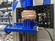
Coil is 5mm turned with an inside diameter of ~18mm and 8,5 turns.
Used the formulas and calculators available, got 5x0,33µF at the ZVS and aimed for 95KHz. Would get about 1.6µH with that coil.
I use a chinese 80A SSR, but I doubt that's where everything fails since the PSU shuts down? Question would be what is bad, PSU or ZVS? Would 12A without anything inside the coil be right? It's not insulated and it's not making contact (shorting).
Hopefully someone might got a clue what's wrong here
I'm not sure if the coil is right due to other factors?
*EDIT* Coil is getting fairly hot without anything in it *EDIT*

You are using an out of date browser. It may not display this or other websites correctly.
You should upgrade or use an alternative browser.
You should upgrade or use an alternative browser.
Induction brass annealer redux
- Thread starter Gina1
- Start date


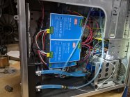
So I connected the ZVS to the PSU without any relay and at first it wouldn't fire but after a couple of tries it actually did. No voltage drop and the amps kept on rising without anything shutting down. The coil got really hot and after a couple of on and offs I burnt off one of the big traces at the back. Seems like the PSU works? Time to get a 2500W board maybe and stop goofing around with this POS 
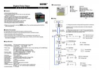
Hello, I have a Sestos Digital Twin delay and I'm not an electronic guy, could someone please describe which wires go to which terminal at the rear of the unit. The power in to 9 and 10 is easy to understand, but where do I input the 48v in and then out of this terminal block?
Attachments

Okay, I'll answer your question directly, then I'll ask some follow-up questions and give some unsolicited advice...Hello, I have a Sestos Digital Twin delay and I'm not an electronic guy, could someone please describe which wires go to which terminal at the rear of the unit. The power in to 9 and 10 is easy to understand, but where do I input the 48v in and then out of this terminal block?
If you want to use the Sestos' internal relay to switch 48 volts and up to 20 amps or so, you would connect the power source to terminal 7 and connect the ZVS board to terminal 8 (the Normally Open terminal that closes during the A cycle of the Sestos timer).
Now the other stuff...
To ensure a more accurate and complete answer, you should probably provide the exact model of your timer (and a link to whatever documentation you have access to).
Next, I personally would not use the Sestos internal relay to switch that much power...it might be able to handle it, but I prefer to use it to control an external relay that is more robust and probably cheaper (so that if there is ever a problem, like the relay fuses shut, you only have to replace a much cheaper component). For example, run 12 volts through the timer relay to trigger a larger double pole relay that connects/disconnects the 48 volt (+ and -) supply to the ZVS.
A couple of other observations from your terminal diagram...there doesn't seem to be a 'Start' terminal, so I'm curious how the timer cycle gets started (I'm guessing that the 'Reset' terminal will stop the timer running). Also, if you are going to have a drop mechanism(solenoid), then you would use terminal 11 for power in and terminal 12 for power out to the dropper. Lastly, from what I can glean from the info provided, is that the 12V and the 0V (terminals 4 and 5) are different options for actuating the switches (terminals 2 and 3), but I'm unsure how they are used, exactly.
Hope this helps...
Edit: PS- here is a link to the manual for the B3S-EN model that I used, for comparison (note the Start terminal on the terminal diagram at the bottom)
Sestos B3S-EN.pdf
 drive.google.com
and an Amazon link...
Last edited:
Many thanks for your reply hdmunger. Sorry, I should've included the model I'm using. Please see below.
Your explanation makes sense even to a non-electronic person like me.
Could you please suggest an external relay that I would be able to buy? I'm in the UK and it's easier to buy from Asian sources than it is to from the USA. The postage and import duty are often more than the item costs.
Your explanation makes sense even to a non-electronic person like me.
Could you please suggest an external relay that I would be able to buy? I'm in the UK and it's easier to buy from Asian sources than it is to from the USA. The postage and import duty are often more than the item costs.
Attachments

O
I also do not think you require a 2500w ZVS board. It would fail as well if powered incorrectly. And AMP uses something like 700W or 800W to anneal cases, usually less.
One thing to take note of is that the 48V needs to be stable before connecting it to the ZVS board, that is part of the reason a relay or SSR is used. The power supply output voltage rise time is extremely slow and that prevents the ZVS from starting to oscillate. Powering your ZVS board by turning the 48V supply on and off (as opposed to connecting and disconnecting it using a "switch") usually results in ZVS failure/destruction. Most likely why yours failed as well.So I connected the ZVS to the PSU without any relay and at first it wouldn't fire but after a couple of tries it actually did. No voltage drop and the amps kept on rising without anything shutting down. The coil got really hot and after a couple of on and offs I burnt off one of the big traces at the back. Seems like the PSU works? Time to get a 2500W board maybe and stop goofing around with this POS
I also do not think you require a 2500w ZVS board. It would fail as well if powered incorrectly. And AMP uses something like 700W or 800W to anneal cases, usually less.
Wasn't 48V and it managed to fire up with wires between PSU and ZVS, it didn't when I used the SSR. Just lit up and then shut down.O
One thing to take note of is that the 48V needs to be stable before connecting it to the ZVS board, that is part of the reason a relay or SSR is used. The power supply output voltage rise time is extremely slow and that prevents the ZVS from starting to oscillate. Powering your ZVS board by turning the 48V supply on and off (as opposed to connecting and disconnecting it using a "switch") usually results in ZVS failure/destruction. Most likely why yours failed as well.
I also do not think you require a 2500w ZVS board. It would fail as well if powered incorrectly. And AMP uses something like 700W or 800W to anneal cases, usually less.
If it didn't oscillate, would it be the reason for the coil to get hot and draw lots of amps?
Could probably just solder it together tomorrow and see if I can get it to work with a switch. I'm having a hard time thinking the board was okey to begin with.
here is the one I got from Amazon:Many thanks for your reply hdmunger. Sorry, I should've included the model I'm using. Please see below.
Your explanation makes sense even to a non-electronic person like me.
Could you please suggest an external relay that I would be able to buy? I'm in the UK and it's easier to buy from Asian sources than it is to from the USA. The postage and import duty are often more than the item costs.
here is the same one on AliExpress: (it looks like a US version of the site, and you may have to search for asian link)
Here is the picture worth a thousand words picture:
DPDT Relay.jpg
drive.google.com
On a separate note, unless you are locked into that model of the sestos timer, I would try to find the model I referenced in the earlier post...that is the one most of us (except the Arduino crowd) are using. It has the cycle Start and Stop capability and the option to loop or not. As near as I can tell, your model starts the A timer when its powered on, and then goes to the B mode until the power is cycled again or the Reset is triggered (or I'm just interpreting the instructions incorrectly). That still means that the B relay switch is basically useless.
Last edited:
I've went with your suggestion for the Sestos B3 model and the relay unit, but in 24v to utilise the power supply I've already fitted.here is the one I got from Amazon:
here is the same one on AliExpress: (it looks like a US version of the site, and you may have to search for asian link)
Here is the picture worth a thousand words picture:
The specs say it is only good for switching up to 28VDC/30Amps, but I've been using mine for 3-4 years now with 48V with no issues. It is a mechanical relay, so there is an audible thunk when it closes...a lot of people don't like that and use a solid state relay (SSR) so it is silent (keep in mind the chinese SSRs are cheap junk and prone to failure...to get a good one, you'll pay more). To me, it is convenient to have that big click periodically while my annealer is running so I know everything is still funtioning normally...no occasional click means something is wrong or the batch is complete.DPDT Relay.jpg
On a separate note, unless you are locked into that model of the sestos timer, I would try to find the model I referenced in the earlier post...that is the one most of us (except the Arduino crowd) are using. It has the cycle Start and Stop capability and the option to loop or not. As near as I can tell, your model starts the A timer when its powered on, and then goes to the B mode until the power is cycled again or the Reset is triggered (or I'm just interpreting the instructions incorrectly). That still means that the B relay switch is basically useless.
Are the three switches shown on the B3 model 'momentary' ones, for start, stop and pause?
Many thanks for your assistance from the other side of the world.
yes, momentary switches...the terminal diagram in the instruction PDF shows a good wiring diagram for the Start, Stop and Gate (pause) buttons.I've went with your suggestion for the Sestos B3 model and the relay unit, but in 24v to utilise the power supply I've already fitted.
Are the three switches shown on the B3 model 'momentary' ones, for start, stop and pause?
Many thanks for your assistance from the other side of the world.
Just remember, that the pause function, if you use it, only pauses the progress of the active timer while the switch is held, it won't deactivate the relay (ie shut off the ZVS board).
I only use it when testing a new batch of brass for an 'accurate' timer duration...I set the heating cycle timer for a few seconds longer than I think it will need, start the timer, and when the brass is heated to where I want it, I press and hold the pause button and tap the button that drops the brass out of the coil, then I can read the elapsed time while it is frozen. Make sure you do this relatively quickly and then press the Stop button so everything shuts off, then write down the elapsed time you came up with for later use on that batch of brass.
Good luck on your build. If you have read through this thread, you have probably already seen my build posts...the original build is post 1858 and last years rebuild is post 2902 (pretty proud of this one).
Last edited:
I have pretty much the exact same experience you have. My current draw at 48V is 13.5A with nothing in the coil. Tried multiple coils, 3.16mm copper pipe 18mm ID 9 turns (inside layer 5 turns, outside layer 4 turns). Same pipe, 20mm ID, 8 turns (4turns 2 layers). The one coil was running at 101kHz the other at 105kHz. My power supply would trip when trying to anneal large cases like .375 H&H. The only reliable way I found to reduce the idle current and thus giving more headroom when actually placing something in the coil, was to reduce the oscillation frequency. Mine is now running at 83kHz and the idle current now is 11.5A and I am able to anneal the .375 cases without the power supply tripping. The coil I now use is 20mm ID, 10 turns (5 turns x 2 layers). All coils were insulated with high heat sleeving.
According to this page (https://spaco.org/Blacksmithing/ZVSInductionHeater/1000WattZVSInductionHeaterNotes.htm) at 100kHz the current draw will be 12A and at 80kHz the current draw will be 6A. So I expected mine to be a lot lower as I am close to 80kHz.
My coil also gets hot even when nothing is in the coil. Make sure you water cool as the heat from the coil is transfered into the board and the caps which causes the caps to fail.
I was also hoping someone can give some insight as the current draw I am experiencing seems excessive compared to what others in the forum are seeing.
I have some empirical insight to add in regards to coil winding that I hope is helpful.
I used this calculator to estimate number of windings and out of about 8 different coils that I tried, 7 of them oscillated within +10/-0khz of my target.
Here's the shameless self plug for my setup:
I am annealing .223 and .308 using a 1kW ZVS board powered by a pair of Meanwell NDR480-24v supplies in series for 20A capacity. The whole thing is controlled by an Arduino Pro Micro mounted in a carrier I've made myself that provides:
- Current sensing
- Voltage sensing
- On/off control with RPM monitoring for one pump and two fans
- Monitoring of one thermocouple
- Mounting for a stepper driver of the kind used in a lot of 3d printers
- Solenoid output
- SSR output
- LCD screen output
- Three isolated button inputs
- Two case presence sensor inputs
If anyone is interested in photos of another take on the rotary case feeder I can post mine. I scratch designed the existing typical concept to go together without fasteners except to hold the motor on.
Now on to the coil testing:
The power supply stack is trimmed to 49.0 volts.
I started with four choices of coil, all double layer made with 3mm (1/8" tubing).
14mm ID/~6 turns each layer, 19mm ID/~4.5 turns each layer, 25mm ID/~3.5 turns each layer and 32mm ~3 turns each layer.
I measured oscillation frequency with an oscilloscope probe held in the air near the coil and the smaller coils were up at 100 or 105khz and the larger coils were around 90khz. Frequency increased 3-5khz as cases were inserted.
My initial thought was to try and minimize the coupling losses to the case by winding the coil ID quite close to the case OD. What I ended up finding was that with the 14mm coil the idle current would fold back the supply. The 19mm coil idle current was almost 15A and inserting a .223 case would also fold the supply. The 25mm coil idle current was like 12A and running .223 or .308 cases increased it about 3-4A. The 32mm coil idle current was 6A and would increase 1-2A with cases inserted.
Running just a few cases I observed that for each smaller ID coil the coil itself heated faster than the next larger size for the same on duration. Also the heating time to get the case to the same temperature increased as the coil ID increased.
Maybe someone can correct me here, but my conclusion is that the smaller the coil ID the more the concentrated the magnetic field and the more it couples to the coil itself, hence the higher the idle current and hotter the coil temps.
I've selected the 25mm coil and I'm heating .223 for 4.6s to melt 1100deg Tempilaq and 6s for .308. The case mouth just starts to glow. With forced water cooling and a ~6s total cycle time for .223 the coil only gets luke-warm to the touch at steady state.
I attached the thermocouple to one of the caps on the ZVS board and it was getting into the 40's C and climbing so I directed one of the 80mm case fans at it and it seems to plateau in the mid to high 30's C.
I've annealed 100 cases of each size, loaded them and the reduction in seating force compared to the previous loading using these 8x fired cases is significant. CBTO length is also much more consistent. Now I have to wait for the paper to tell it's tale.
Augi
PS Thanks to WildBill who helped me out with a DOA ZVS board. I originally got one of the ones with the square heat sinks and it would oscillate but folded the supply instantly with anything inserted into any size coil. I ordered one with the angled heat sinks and it works great, so here's confirmation of that problem.
Kudos for you experiments. I abandoned the coils long time ago. I just did not want to deal with liquids in my built. Instead I use Fluxeon hard core inductors. The magnetic flux is highly concentrated. Idle at 44-48 volts, the current reading is 9-11 Amps. With 284 Winchester case, the current reading is 14-16 Amps and 1000F is reached for 3.5-3.8 sec. By the way, after reaching the 1000F, I continue the annealing. maintaining that temperature (subject - extensively discussed discussed in this forum). I have used different rated ZVS-s with similar results.
With two 120 mm cooling fans. I've never experienced overheating. The only sensors I've used are voltage, amps and flame. I'm considering presence sensor, since I'm including case feeder and I'd like to take your offer of showing some details of your built (If you prefer, PM is OK)
PS I was considering to include interchanging coil in this project, but for now I will postpone my desision.
Last edited:
So you made those coils yourself or did you buy it? Give us some info pleaseKudos for you experiments. I abandoned the coils long time ago. I just did not want to deal with liquids in my built. Instead I use Fluxeon hard core inductors. The magnetic flux is highly concentrated. Idle at 44-48 volts, the current reading is 9-11 Amps. With 284 Winchester case, the current reading is 14-16 Amps and 1000F is reached for 3.5-3.8 sec. By the way, after reaching the 1000F, I continue the annealing. maintaining that temperature (subject - extensively discussed discussed in this forum). I have used different rated ZVS-s with similar results.
With two 120 mm cooling fans. I've never experienced overheating. The only sensors I've used are voltage, amps and flame. I'm considering presence sensor, since I'm including case feeder and I'd like to take your offer of showing some details of your built (If you prefer, PM is OK)
PS I was considering to include interchanging coil in this project, but for now I will postpone my desision.
")
Update on my build. Fixed another coil which is larger and it started to "work". The board would cut off but if I switched it on again it could heat up some brass. It took forever so I tried with another coil which worked "okey" but only when it was cool. When it got up to temp after one case it would fail and shut down (the board not the psu). Seriously think the board is busted somehow? I had to repair the burnt traces underneath which seems to be working out pretty okey tbh.
So you made those coils yourself or did you buy it? Give us some info please

Kudos for you experiments. I abandoned the coils long time ago. I just did not want to deal with liquids in my built. Instead I use Fluxeon hard core inductors. The magnetic flux is highly concentrated. Idle at 44-48 volts, the current reading is 9-11 Amps. With 284 Winchester case, the current reading is 14-16 Amps and 1000F is reached for 3.5-3.8 sec. By the way, after reaching the 1000F, I continue the annealing. maintaining that temperature (subject - extensively discussed discussed in this forum). I have used different rated ZVS-s with similar results.
With two 120 mm cooling fans. I've never experienced overheating. The only sensors I've used are voltage, amps and flame. I'm considering presence sensor, since I'm including case feeder and I'd like to take your offer of showing some details of your built (If you prefer, PM is OK)
PS I was considering to include interchanging coil in this project, but for now I will postpone my desision.
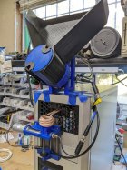
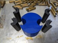
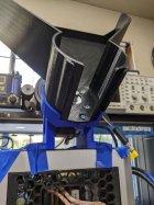
Here's a link to a video and I've attached some photos. Pardon the blue tape, the last thing I have to do is drill holes and bolt the feeder to the top of the computer case.
This is sized to handle from .223 up to .338 size cases. There are quick change inserts in the drum as well as a conical insert above the trap door to match each case diameter. The trap door is also height adjustable via a thumb screw.
The software protects against:
- Over current
- Under voltage
- Feed Jam
- Double Feed
- Coolant over temperature
It will also automatically detect and recover lost steps if the feeder gets wedged picking up a case and misses a few.
My goal was to build an automatic machine, but this is not something I would take my eyes off of while operating. I had one case of a firmware crash during development that left the heater running indefinitely. That melted a case in half and also melted a hole in the trapdoor in about 10 seconds. Also occasionally (2 or 3 in 100) a case will get hung up in the coil and I'll have to poke it with a screwdriver to get it to settle on the trap door.
If I were to roll a new control board I would have a watchdog timer monitoring the fet that controls the heater to guarantee 100% it turns off if the Ardunio goes braindead.
Augi
Attachments


Similar threads
- Replies
- 74
- Views
- 47,299
- Replies
- 0
- Views
- 1,572
Upgrades & Donations
This Forum's expenses are primarily paid by member contributions. You can upgrade your Forum membership in seconds. Gold and Silver members get unlimited FREE classifieds for one year. Gold members can upload custom avatars.

Click Upgrade Membership Button ABOVE to get Gold or Silver Status.
You can also donate any amount, large or small, with the button below. Include your Forum Name in the PayPal Notes field.
To DONATE by CHECK, or make a recurring donation, CLICK HERE to learn how.
Click Upgrade Membership Button ABOVE to get Gold or Silver Status.
You can also donate any amount, large or small, with the button below. Include your Forum Name in the PayPal Notes field.
To DONATE by CHECK, or make a recurring donation, CLICK HERE to learn how.