You are using an out of date browser. It may not display this or other websites correctly.
You should upgrade or use an alternative browser.
You should upgrade or use an alternative browser.
Induction brass annealer redux
- Thread starter Gina1
- Start date
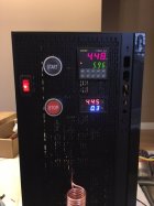
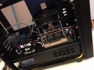
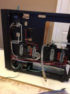
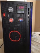
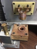
Coil not heating up. I've checked the wiring and every thing seems to be working. Timer is working. Power is getting to the heating board but for some reason I'm only getting 0.3 Amps to 1.1 Amps when the it goes through the annealing cycle. Bad power supply? Bad induction board?
Attachments
Last edited:
itchyTF
Gold $$ Contributor
Put a different load on the power supply like a suitable resistor or lamp to see if current is correct. I believe you should see about 300ma of current with a 100 watt bulb. If that works it might be the induction board.Coil not heating up. I've checked the wiring and every thing seems to be working. Timer is working. Power is getting to the heating board but for some reason I'm only getting 0.3 Amps to 1.1 Amps when the it goes through the annealing cycle. Bad power supply?
I'm using 48V 12.5A power supply. I have confirmed that 44V is being supplied past the Packard C230. It only goes down to 4.5V at 300mA when it is on induction cycle.What Voltage power supply are you using it is showing 4.5V at 300 mA Si it is very loaded down. It indicates a short on the induction board. Are the heat sinks touching each other or something else. This was the problem a recent poster found.
I followed the schematic of Gina1. It calls for Packard C230 2 Pole 30 Amp Contactor, 120 Volt Coil. No, the coils are not touching.What's the Packard C230?
Not knowing the schematic for the induction board, I'll assume the 48v isn't applied to the switching fets/transistors when not doing induction. If that's the case the induction board may still be bad.
Are any turns of the coil touching?
They will be now but what caused the board to not oscillate in the first place? All the diodes need to be checked along with the resistors and the inductors. The boards are not high quality and many have cold solder joints on the inductors.My guess is bad FET(s) / transistor(s).
Did not have a 100 watt bulb but decided to attach a 115V 1.12A motor to Packard Contactor. The voltage meter now goes as high as 6.9 to 7.1A at 48V. So that means there is something wrong with the induction board. Ordered a replacement and will return the damaged board.Put a different load on the power supply like a suitable resistor or lamp to see if current is correct. I believe you should see about 300ma of current with a 100 watt bulb. If that works it might be the induction board.
Attachments
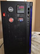
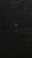
I have a few questions regarding the coil. The PC case I used has has a metal grill at the front. Can I drill small wholes on the plate for copper tubbing to pass through and place rubber nipples around the copper tubing for insulation, or should I just cut a big square whole for the copper tubing to pass through? How much clearance is needed?
Attachments
I don't know if can or can't. While messing round trying to fix the issue with first board I forgot to replace the coil, it make a loud noise when it went through the annealing cycle. This time I just attached the new board from outside the case just to make sure that it wasn't touching anything inside the case and still the same results. Now I'm wondering if that first board was damaged to begin with. Unfortunately I wouldn't know how to test it. Everything else is working fine. Could it be my power supply or the contactor? I attached a 115V 1.12 Amp motor and it drew as much as 7.0A at 48 volts. HELP!A second bad board?
Can those boards be run with no coil without damage? If so, try it.
Similar threads
- Replies
- 74
- Views
- 47,348
- Replies
- 0
- Views
- 1,573
Upgrades & Donations
This Forum's expenses are primarily paid by member contributions. You can upgrade your Forum membership in seconds. Gold and Silver members get unlimited FREE classifieds for one year. Gold members can upload custom avatars.

Click Upgrade Membership Button ABOVE to get Gold or Silver Status.
You can also donate any amount, large or small, with the button below. Include your Forum Name in the PayPal Notes field.
To DONATE by CHECK, or make a recurring donation, CLICK HERE to learn how.

Click Upgrade Membership Button ABOVE to get Gold or Silver Status.
You can also donate any amount, large or small, with the button below. Include your Forum Name in the PayPal Notes field.
To DONATE by CHECK, or make a recurring donation, CLICK HERE to learn how.


