Follow along with the video below to see how to install our site as a web app on your home screen.
Note: This feature may not be available in some browsers.
This Forum is for adults 18 years of age or over. By continuing to use this Forum you are confirming that you are 18 or older. No content shall be viewed by any person under 18 in California.
Well I must admit that I feel pretty much defeated at this point. Maybe I bit off more than I could chew. It's the first time I attempted something this complex. I took my time made and double checked my wiring. Everything else is working except the induction board.
Not really electronically inclined I'm not sure what to do next. The induction board was replaced and the was connected after the Packard Contactor first and then directly to the power supply. In both situations the coil did not heat up.
When connected as intended the board only draws 4.005V at 0.3A. This was the case for both inductions boards. Someone suggested I attach a 100Watt bulb but I didn't have one. I did have was a 115V 1.12A motor. When the annealing cycle is on, the motor would draw 47.8V at 6.7 to 7.0A.
I would not even begin to know how to test the components of the board. Given the available information, what should I do? Buy yet another board? Do I buy a new power supply?
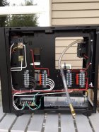
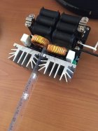
Maybe it just me...but there look like there are entirely too many wires going into that relay. Mine only has 6...48V +/- IN, 48V +/- OUT, and 12V +/- (controlled by the timer) to power the relay closed.
Also, I never used the resistor bridge you have across the top of the relay and have never had any issues...maybe try with that removed for a test to see if that changes anything.
NearZero - I feel your pain! Being a (retired) test engineer (electronic) I've been through numerous situations debugging problems. Maybe that's why I don't have as much hair as I used to. A lot of times when you find the problem the response is DUH, why didn't I see that before? Software too, although software only does what you tell it to do. Even though you swear you're not telling it to do anything wrong.
Do you have an ohm meter? How are your soldering skills?
Maybe it just me...but there look like there are entirely too many wires going into that relay. Mine only has 6...48V +/- IN, 48V +/- OUT, and 12V +/- (controlled by the timer) to power the relay closed.
Also, I never used the resistor bridge you have across the top of the relay and have never had any issues...maybe try with that removed for a test to see if that changes anything.
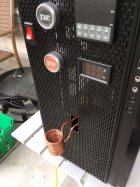
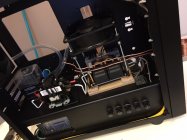
The wire going into the Contactor are + & - from 48V power supply and a smaller black wire to the V/A meter display. Wires going out of the Contactor are + & - 48V to the induction board. The other two wires are for the annealing LED indicator light. The black wire in the front of the contactor lead to the Sestos Timer and the light green wire is a ground wire.
Anyway, I disconnected the Varistor 130VAC as you suggested and the LED light for good measure. Same thing. Only about 4.05V and 0.3A is being drawn by the induction board.
Well, I can't say that I'm throwing in the towel. I put in so much effort into this thing. The frustrating thing is that I just can't the board to work. Like I said, this is the second board already.
Try removing the additional wires, that go to the V meter. Just have the ones that go to the ZVS board. Use the basics if that works add the other bits back in and see if that stops it working.
Maybe bypass the relay? is the relay working?
Disconnect the zvs board and put your multi meter across the outputs of the relay then press the start button, you should get DC volts.
As above never fire up the ZVS board without a load on the outputs ( the coil in this case)
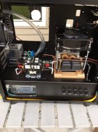
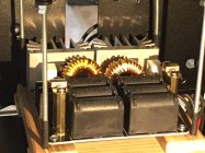
Make sure that neither of your heatsinks are touching ground. Use your multimeter on ohms between the case which you should have grounded and the heatsink it should be open if you find a low ohms reading then look for the cause.
Are you open to repairing the board by replacing components or going for another board swap? I am sure many posters on this topic could put a bit of a step by step guide to fault finding the board. I have been through the process a couple of times but never took any notes as I went.
The relay switching quickly and cleanly is important the full voltage needs to be applied not a ramp up or interrupted input voltage.
Try removing the additional wires, that go to the V meter. Just have the ones that go to the ZVS board. Use the basics if that works add the other bits back in and see if that stops it working.
Maybe bypass the relay? is the relay working?
Disconnect the zvs board and put your multi meter across the outputs of the relay then press the start button, you should get DC volts.
As above never fire up the ZVS board without a load on the outputs ( the coil in this case)
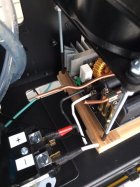
I actually took the ZVS board out and wired it directly to the 48 volt power source. I placed the placed the ZVS board on top of a block of wood to make sure there were no grounding issues. I powered it up and not heating occurred.
If what you mean by relay is the Packard Contactor, I believe it work because the there is a voltage change when the annealing cycle occurs. Or is there something wrong with my assumption.
I did accidentally fire up the ZVS board w/o the coil, but that was the first board and that was after I messing about trying to get it to work. That is it was hooked up properly but did not work and I forgot to replace the coil while I was trying to solve the problem. That did not happen with the second board. The coil was always hooked up.
I did remove the Varistor and the LED. Still did not work.
As for the tidy wiring, that's attributed to my OCD tendencies.
Could it be poor contact of the coil since I did not solder the 1/8 coil to larger brass tubing like most of you have? I have seen other builders not do that and it worked for them. How can I measure the amp output of the power supply.
Make sure that neither of your heatsinks are touching ground. Use your multimeter on ohms between the case which you should have grounded and the heatsink it should be open if you find a low ohms reading then look for the cause.
Are you open to repairing the board by replacing components or going for another board swap? I am sure many posters on this topic could put a bit of a step by step guide to fault finding the board. I have been through the process a couple of times but never took any notes as I went.
The relay switching quickly and cleanly is important the full voltage needs to be applied not a ramp up or interrupted input voltage.
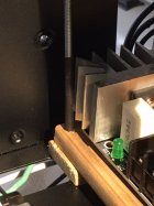
The heat sink are definitely not touching. there is enough space between them to I placed a plastic ruler. The board on a wooden platform and I placed heat shrink on the long metal screws holding the 110V cooling fan above the board to make sure that there is no grounding, if that's the right term. going on. There is also a fair amount of distance between the heat sink and the back of the computer case.
As for messing about the board to do repairs, I think I'd best order yet another board.
Try removing the additional wires, that go to the V meter. Just have the ones that go to the ZVS board. Use the basics if that works add the other bits back in and see if that stops it working.
Maybe bypass the relay? is the relay working?
Disconnect the zvs board and put your multi meter across the outputs of the relay then press the start button, you should get DC volts.
As above never fire up the ZVS board without a load on the outputs ( the coil in this case)
Yes, I did disconnect the ZVS board and checked the out flowing voltage of the Packard Contactor. I cranked the power supply to the full (49.7V) according the reading of the multi meter display in front of the computer case. I used my multi meter to measure the out going voltage from the Packard Contactor and it would read 49.3V each time the annealing cycle would come on and go to 0.0V each time the cycle ended.
Could it be poor contact of the coil since I did not solder the 1/8 coil to larger brass tubing like most of you have? I have seen other builder not do that and it worked for them. how can I measure the amp output of the power supply.
This Forum's expenses are primarily paid by member contributions. You can upgrade your Forum membership in seconds. Gold and Silver members get unlimited FREE classifieds for one year. Gold members can upload custom avatars.
This site uses cookies to help personalise content, tailor your experience and to keep you logged in if you register.
By continuing to use this site, you are consenting to our use of cookies.