Thanks Groc I'll go w that one.
Hi all. I'm starting my build.
I couldn't find a "DROK Digital V/C measurement DC 0-100V/50Amp meter" for sale that seemed to match Gina's build. Is there a replacement device that would do the trick? How about this one?
https://www.amazon.com/gp/product/B017BCXQO6/?tag=accuratescom-20
thanks
The unit listed by GrocMax, looks like a good match. Most likely made by the same manufacture, just different name brand.
Good luck on your build Bill. If you need any advice or help, feel free to IM.
Gina
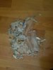
Lesson Learned !!! 
Was annealing a bunch of old fired brass that had been sitting around for a months.
Lesson learned... ALWAYS check for unspent primers. This primer/round went off after it had dropped from the trap door into the pyrex catch dish.
Luckily I didn't get hit with any flying glass.
-
primer1a.jpg
241.2 KB
· Views: 340
Lesson Learned !!!
Was annealing a bunch of old fired brass that had been sitting around for a months.
Lesson learned... ALWAYS check for unspent primers. This primer/round went off after it had dropped from the trap door into the pyrex catch dish.
Luckily I didn't get hit with any flying glass.
Not just the glass. The anvil or cup could go deep into your eye.
Not just the glass. The anvil or cup could go deep into your eye.
LOL, Just like Christmas Story, Ralfie "you'll shoot your eye out"
By the way safety glasses help, which I was wearing.
Thanks to you all for sharing your ideas to everybody.
GinaErick now reached Germany.
I started several monthes ago to build my induction annealer with the same PCB (1000W/20A) incl. delivered coil and a cheap PS (48V/10A).... and it is still alive.
But I was not satisfied with it, because the annealing time was to long (approx. 24sec for .308) and the whole case was to hot (450F Tempilaq).
In the meantime some of your proposed parts arrived and I will start soon to turn my "flying wiring" into a GinaErick!
The challenge I have is to get some of the parts here in Germany...especially some parts in inch ;-)
- Mike
Hi Mike...
Even with a 10 A power supply 24 seconds is way too long for a .308 case. Should be about (approx) 5-6 seconds That is the neck and maybe 7mm past the shoulder @ 750 degrees F
If your using the same inductor PCB, two things come to mind. With 1/8" tubing the inside diameter of the coil should be 1 1/8" (8 turns) Anything larger and it will take more time to heat up the case.( Neck and shoulder)
Do you have the volt/amp meter wired into your circuit ? Without it your kind of flying blind, to set the correct current for annealing. If you watch the you tube video at the beginning of this thread, you can see that the trap door height is adjustable. This does two things. Sets the height for different cases, but most importantly is sets the current limit for the annealing.
In your case with a 10 amp PS, your limit is 10 amps. If your going to build it like mine (from the video) The way you set it up, is to do the following....
(1) drop the trap door down, so the none of the case is in the coil.
(2) set timer "A" for about 60 seconds.
(3) hit start button
(4)with the unit annealing slowly bring the trap door up with a case in it. Watch the current on the amp meter. When you hit 10 amps, lock the trap door into place and hit the "stop" button. Don't wait too long or you will have a melted case.
(5) this is your current limit for that type of case
((6) reset timer "A"... Paint a case with "Tempilaq" 750 degree F, 399 C indicating fluid. Start playing around with timer "A" . Starting with 3 seconds and increasing the time until the tempilaq starts to change color. Once you get the color change to where you want it (in my case, I like it 1/4" past the shoulder). This is the annealing time.
(7) now you are correctly set up for that case. You now can switch over to auto-recycle and start annealing one case right after another.
Hope this works out for you. I'm always glad help out.
Gina
Thanks to you all for sharing your ideas to everybody.
GinaErick now reached Germany.
I started several monthes ago to build my induction annealer with the same PCB (1000W/20A) incl. delivered coil and a cheap PS (48V/10A).... and it is still alive.
But I was not satisfied with it, because the annealing time was to long (approx. 24sec for .308) and the whole case was to hot (450F Tempilaq).
In the meantime some of your proposed parts arrived and I will start soon to turn my "flying wiring" into a GinaErick!
The challenge I have is to get some of the parts here in Germany...especially some parts in inch ;-)
- Mike
Just use the closest metric equivalent, 1/8" copper tubing = 3mm, etc.
Thanks Gina and GrocMax,
in my previous setup I used the coil that came with the PCB (ID approx. 1,9 - 2,0"), tube OD approx. 1/4".
I had an amp meter installed and the current never reached 10A even with the whole braas case in the coil (only for testing). Only with a screwdriver I could exceed 10A.
Anyway, because I like your ideas here in the thread and they are already tested ;-) I decided to go the path of least resistance and ordered the proposed MeanWell PS with the option to limit the current and some of the other stuff.
For the coil I bought 4mm tube (a little bit more than 1/8") because that was locally available.
I will come back and will report once I've finished.
For me the mechanical part is the horrible part....
- Mike
Mike...
One of the reasons for using the 1/8" tubing, was after you have 8 turns, is the height of the coil. In your case, with 4mm tubing, you will have a taller coil. Since your going to be annealing .308 case this my not cause any problems. Hollywood who designed the original coil came up with the working spec's and that is what I've used.
Again.... The important thing, when you make your coil is the 1 1/8" inside diameter of your coil. One of the reasons, it takes so long to heat up a case, using the coil that came with your PCB is the large ID of that coil. In induction annealing, the closer the case is to the coil, more magnetic energy is transferred to the case, the faster it gets hot. Also remember to make sure none of the turns in your coil are shorted.
By the way, do NOT stick a screw driver in your new coil. (or any iron or steel items) I was curious, shortly after I built mine and inserted a small screw driver in the coil to see how much current it would draw. All metal jeweller's screw driver. In less than 1/2 second I burnt my fingers and blew the inductor PCB.... A word to the wise
Good luck Mike
Gina
3mm = .118" 4mm = .157"
1/8" = .125"
4mm will be more forgiving for pump/coolant flow rate and pump head required.
With current limiting the 4mm will probably be fine, and you can stick a big ol' piece of iron in it with zero damage, the only thing that may happen is tripping a PS undervoltage fault (less than 5v) which requires a shutdown reset.
Without the current limiting ya gotta be real careful on coil dimensions and workpiece as Gina stated.
Here's a demo of the current limiting using a big steel nutdriver shaft at higher settings then switching to a screwdriver so the undervoltage fault didn't get tripped-
Well, I also want to anneal .223 cases.
Do you think the coil will be to high when using a 4mm tube?
Any experience with a detachable/exchangable coil?
First idea was soldering a T-fitting to the end of the coil.
Soldering a banana connector to the other end of the T-fitting (so that no liquid cooling can pass through).
The induction board is connected via wires to the corresponding socket in the case.
The liquid cooling is connected outside the case (similar to Annie).
Any other idea?
- Mike
BTW, Please feel free to correct my english ;-)
Well, I also want to anneal .223 cases.
Do you think the coil will be to high when using a 4mm tube?
The GinaErick build is everybody's build. Just as GrocMax took the original GinaErick design and made it a constant current induction annealer (by changing out the power supply and adding additional circuitry) he made an improved build.
As far as I know, no one has added a changeable coil. It's a good idea for small to very large cases. You could be the first to do it. (coil height and ID)
Another thought... Hollywood's original coil was 8 turns of 1/8" tubing. With your 4mm tubing why not try 7 turns ?
If you go that route, let us know how it works out.
Gina
PS English !!!.... Shucks, if it were not for the spell check, I don't think my writing/posting would be understandable. I'm the last one to correct to some one's English.
You can keep coil inductance the same and shorten it by putting cancelling loops in it. So it would still have 8 turns but only be 6 turns tall effectively. This video shows a cancelling loop at the top of the work coil-
Or use the 3mm tubing which is closest to silly Yankee imperial size of 1/8".
Compression fitting is probably the cheapest way to get a changeable coil, but the coolant must be drained during changes.
G'Day Gina
What a ripper of a system much more precise than using a flame.
Built my own on your system. Went to give it a test run, well not so good. With nothing in the coil as soon as I powered it up the induction circuit drew full load current around 18A, then the relay burnt out. The 48v 600w power supply couldn't handle it and went into limiting mode.
So I think I may have had a fault zvs board or the switching relay was to slow, which I have ordered another zvs and upgraded the relay. Now have installed a 3 phase contactor that will handle the current no issue's. As the induction circuit needs a sudden hit of power to make the transistors to start switching thus the tank circuit to sing / reasonate so to speak. I'm starting to think the relay may have been the problem all along.
Anyway waiting on a new board and will try again.
So heads up guys when switching the supply to the induction board make sure your relay will for sure handle the current. Also make sure it switches fast. Also with switch mode power supply's make sure the power supply is up and running, do not switch the supply power to the power supply, must switch the output. As a switch mode power supply will not ramp up fast enough thus burnt out transistors on the induction board.
Cheers
WOW.. Never heard of that happening with one of these builds. I guess you've got it figured out what happened. Just make sure none of your coil turns are shorted. For the most part for the basic GinaErick build, current draw with no case in the coil is about 8.6 amps.
And yes, your 48 volt PS has to be up and stable, when the contactor/relay applies power to the ZVS PCB.
Good luck, and let us know how it's going.
Gina
What did you use for the enclosure?
Thanks
My hopper is now working and PLC program pretty close. Minor debugs and tweaks are all that's left. Six seconds at 12.6 amp draw seems perfect for my 6xc brass! The video shows it operating in test mode so no annealing actually being done
") View attachment 1002044
View attachment 1002044
What did you use for the enclosure?
Thanks
Very Nice !!! Nice looking unit. My enclosure is a very simple 1/4" plywood cover. 3 sided with vent holes in the sides and back, and one large vent hole with fan guard on top for the fan/ZVS PCB.
6 seconds is about what I get for 6XC with the 12.5 amp (600 watt) power supply.
Once again, you did a beautiful build.
Gina


