• This Forum is for adults 18 years of age or over. By continuing to use this Forum you are confirming that you are 18 or older. No content shall be viewed by any person under 18 in California.

Induction brass annealer redux

So I just completed my GinaErick case annealer. I just followed the instructions on the first page of this post and used the parts list to create my version. Electronically it is exactly the same as the original. Why mess with a working formula. Beside my area is mechanical rather than electrical.

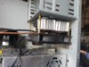
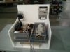
The enhancement I made was on the trap door system and added a case guide. The trap door system is on a platform that can move up and down to adjust for case length. One I have the height adjustment for a particular caliber I can mark the location of the indicator on the side of the housing. This just makes for more consistent application of the location. I can quickly move the platform up or down using the hand wheel located next to the coil. The platform moves up and down using a lead screw and linear guide bearings. This allows the case neck to be presented to the coil for everything from 6PPC to 338 Lapua. Once you have the timer adjustment and the platform height defined you can go back to the same settings in just a few seconds with no guess work each time you setup.

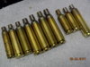
The other enhancement was to add a UHMW bushing to guide the case to the trap door. Bushing were made from bar UHMW and bored to the size of the case. Since the exposure to heat is only coming from the case neck the bushing are not having any problem surviving at all. For this I bored the hole for the case out to 3/4" to carry the UHMW busing. All of the bushing measure 3/4" dia OD with a thru bore to match the case size. Cases drop out the front into a small metal baking pan.

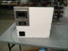
The entire unit measures 8" wide, 19" tall and 18 inches deep. Attached are a few images of the completed unit. Just wanted to share my experience. This is an awesome little annealer!!! Cost of the project was some place around $500. Guts of the project were around $300. The case, bearing and leadscrew drove the cost of the project up. I know other are using PC cases which is keeping cost much lower but I like the industrial look of this type of enclosure.

Besides none of us have gotten into this hobby to "save" money.

View attachment 1001297 View attachment 1001298 View attachment 1001299 View attachment 1001300 View attachment 1001301

I love it! Great work :-). You may end up swapping your pump/tank and radiator locations to get the reservoir at the highest point for trapped air. I struggled a bit with mine. Again, great job; love the lead screw assembly!
 
Bert,

I did some SPICE analysis to bolster my WAG a bit and with an arbitrary 31 VAC from the transformer, and a load of 10 Amps a 5,000uF capacitor will result in about 2.8V RMS ripple on the 40 Volt output. If you are using a Royer Oscillator for the RF drive to your work coil, that ripple should not be a problem. And, most inductance heaters do use a version of a Royer.
With the relay to the oscillator not closed, the DC voltage will be about 42 volts or so and when the relay picks, it should easily start the oscillator in a safe mode i.e. only one transistor taking the lead on startup. The relay should have no problem with the current drawn by the oscillator if the relay is rated at 15-20 amps. When considering that a 10 Amp rated relay can safely handle a heavy start-up current for a short while, say a few mS.
If you do use both capacitors and inductors to filter the DC supply to the oscillator, that can be done, but the appropriate inductors can get quite expensive and the extra complexity is unwarranted.
 
Pingo, a couple things make copper better than brass. Copper is readily available and the resistance of brass is 3.57 that of copper!
That means the electrical losses and heat build-up will be much higher with Brass.
 
Pingo, a couple things make copper better than brass. Copper is readily available and the resistance of brass is 3.57 that of copper!
That means the electrical losses and heat build-up will be much higher with Brass.

Ok, then it make sense that my circuit gets hot and there is "no" engergy transferred to the case, thanks for the quick reply.
 
In my build, I get arcing across the relay contractor. The arching destroys the relay. What am I doing wrong? Thanks.

Go back a few pages on this thread. There was a discussion about relay arcing. Really need to know what type of relay you are using.
 
In my build, I get arcing across the relay contractor. The arching destroys the relay. What am I doing wrong? Thanks.
I have already gone through that same problem.
Several options are available to solve it.
If you are using a single pole relay, make sure that the distance of the open contact is above 1,5 mm. Closer distance between contacts may take you to a big-long-lasting-spark, thus destroying the relay.
Another alternative is to use a double contact relay, making sure that the distance between both contacts is equal, pair to pair. The idea is to have both contacts opened at the same time, to avoid any return current.
I've also tried to use a mosfet instead, but I must have done something wrong, because I couldn't succeed.
 
I have read through the tread and have built up several "kiss" annealers. They work exceptionally well. One unit uses the induction oscillator board in the original build list, powered by a 24V 480W power supply. The second unit uses a 50A -4 mosfet- 8 cap oscillator board (ebay purchase), powered by 36V - 1000W power supply. My question concerns annealing times. My times are significantly shorter. The 36V powered inductor will anneal a .223 case in 0.9 secs and a .308 in 1.2. Both cases are annealed about 1/4" below the shoulder via height adjustment within the coil. The current draw is 24 - 26A during the timed cycle. My 24V unit will do the .223 cases to down to the 1/4" level in 2.2 secs. I have annealed over 3000 .223 mil cases and these are not a concern as these can be throw away. I shoot a 6BR and a 6.5 -284 40X switch barrel with lots of case prep. I have not annealed these as they are already reloaded. I do not want to risk damaging them when I do anneal them. Is this comparatively fast heating over stressing my cases? Is there a consensus as to what a good power on time is?

For clarification- The work coils I use are: 24V unit - 1/8" copper, 5/8" ID glass fiber tube wrapped, 4 turn inner + 4 turn over coil (8 turn total) 36V unit - 1/8" copper, 5/8" ID glass wrapped, 6 turn inner + 5 turn over coil (11 turns total). I have made up a variety of work coils, both ID and turns that will extend the cycle times.

The smaller the ID of the coil, the closer the case is to the coil the more magnetic energy is transferred to the case, hence the shorter annealing times. If you want more annealing time with lower power, building up to the annealing temperature, wind a coil as discussed in the beginning of this thread. I understand your set up is different, from the original "GinaErick" annealer, but the coil diameter is the key.
Gina
 
A longer time gives a bit more control, I think it does a better job (between 5-7 seconds). All the OEM coil only (no flux concentrator) systems I've found vids of use about that time.

25A is a lot of power, a current limit sure helps simplify the time tuning for different cases using the same coil.

Maybe your 1000W unit could run 2 coils at once? 1000W is a lotta power! Someone who's a lot stronger in inductor theory could help out here but seems like two 4 winding coils wound opposite, side by side might work.

Definitely try some larger ID coils, the farther away the case is from the coils the less inductive power gets transferred. Could also try some shaped coils, with cancelling loops. Imagine a shape like a nuke cooling tower, but the 2nd loop from the bottom is 1/2" larger ID, bends the flux lines at the bottom and cancels out heating without changing inductance. You can also cancel out by changing loop direction, CW to CCW.
 
Last edited:
Thanks for the responses. Just to clarify .... I have no issues with the control of the temperature. My time on is controlled by an Omron digital controller to 0.1 sec. I am not sophisticated with my case insertion into the coil. I have made shim blocks of various thickness that I use to position the case. I have old culled cases that serve for my setup. As an example ... I have numerous mil 223 cases that were dented or neck damaged. I set a case so that it is inserted 1/2 to 2/3 of the coil height. I set a cycle time and darken the room, activate the annealer through my proximity switch and look for the neck to just glow red. I insert another cold case, backing down the timer 0.1 sec at a time until there is no glow. At that point I check how far the down the case has annealed. If to far, I remove shimming to lower the case and recheck. When I get my timing and shimming to my satisfaction, I record the data for that cartridge. I believe I can control the necessary parameters. However, my "stop line" on the case body is very distinct compared to photos posted in this thread and factory brass. The photo from left to right: mil 223, 22-250, 22-250AI, 6.5X55, 6mm Rem, 257RobAI, 7mmX57, factory 6Br Rem, 6Br Lapua, 6.5X284 Lapua.

My question is about the thermal shock the case is experiencing during a very short cycle time. Is there any information or experience with case life under short vs. long cycle times to reach annealing temperature?
 

Attachments

  • DSCN0560.jpg
    DSCN0560.jpg
    144 KB · Views: 210
I think only a only a metallurgist specialist could answer your questing. Check with your local university.
 
Just an update for my unit, done approx. 8000 cases now, 12v Tyco relay shows no signs of problems. Optical switch has been 100% reliable. Cooling system is 100% can anneal as fast as possible multiple hundreds of cases. Only change I might make is to extend the current control down to 8A by swapping in some different resistors into the switch resistor array.
 
Just an update for my unit, done approx. 8000 cases now, 12v Tyco relay shows no signs of problems. Optical switch has been 100% reliable. Cooling system is 100% can anneal as fast as possible multiple hundreds of cases. Only change I might make is to extend the current control down to 8A by swapping in some different resistors into the switch resistor array.

Thanks for the update. You did build a nice machine.
 
This is in the works. Need to mount my coil holder on the front face and build a trap door assembly. Build a coil or three and run coolant lines. Some simple wiring needs to be completed also.

4.3" HMI and an Allen Bradley micro 820 PLC for controls. Should make for some fun programming. Once this is operational by manual feeding. I will build an automated feeder with one of the two ideas I have.
 

Attachments

  • IMG_20170308_170734.jpg
    IMG_20170308_170734.jpg
    200.8 KB · Views: 564
  • IMG_20170308_170723.jpg
    IMG_20170308_170723.jpg
    248.6 KB · Views: 547

Upgrades & Donations

This Forum's expenses are primarily paid by member contributions. You can upgrade your Forum membership in seconds. Gold and Silver members get unlimited FREE classifieds for one year. Gold members can upload custom avatars.


Click Upgrade Membership Button ABOVE to get Gold or Silver Status.

You can also donate any amount, large or small, with the button below. Include your Forum Name in the PayPal Notes field.


To DONATE by CHECK, or make a recurring donation, CLICK HERE to learn how.

Forum statistics

Threads
165,279
Messages
2,192,324
Members
78,784
Latest member
Vyrinn
Back
Top