You are/were an EE or similar though, right? Btw, thanks for putting that information together and putting this information out there. It reminded me how much I enjoy tinkering!Sorry not the basic GinaErick design, can't help you. Beyond my pay grade.
Gina
Install the app
How to install the app on iOS
Follow along with the video below to see how to install our site as a web app on your home screen.
Note: This feature may not be available in some browsers.
You are using an out of date browser. It may not display this or other websites correctly.
You should upgrade or use an alternative browser.
You should upgrade or use an alternative browser.
Induction brass annealer redux
- Thread starter Gina1
- Start date
itchyTF
Gold $$ Contributor
- Trigger Signal Source: High voltage level trigger (3.0V~24V), signal ground and system ground are not on common ground to improve the system's anti-jamming capability (you can also connect them on common ground).
Anti jamming?
Also says timer is rated for 400W.
I’m assuming the device with the white label is the ammeter. How do you get a reading? Is there a display on the other side?
- Trigger Signal Source: High voltage level trigger (3.0V~24V), signal ground and system ground are not on common ground to improve the system's anti-jamming capability (you can also connect them on common ground).
Anti jamming?
Also says timer is rated for 400W.
Got it figured out. The timer is misrepresented on the listing.
I picked up a 12v 30A relay at AutoZone to test the wiring of the ammeter. With the timer activating the relay instead of the coil itself, it works as it should. .
Unfortunately, I got only one case cycle out if the relay. It welded the inner relay contacts, stayed on, and melted my case.
So, I've got to order a relay and snubber. How about this relay and this snubber?
Ssr relay
Snubber
If you are going to order some cheap SSR buy one which is rated twice what you need. They are rarely working at advertised specs and are often only made for half of what they are advertised as.Got it figured out. The timer is misrepresented on the listing.
I picked up a 12v 30A relay at AutoZone to test the wiring of the ammeter. With the timer activating the relay instead of the coil itself, it works as it should. .
Unfortunately, I got only one case cycle out if the relay. It welded the inner relay contacts, stayed on, and melted my case.
So, I've got to order a relay and snubber. How about this relay and this snubber?
Ssr relay
Snubber
Check Youtube when they take 'em apart and check what's really in them.
If you are going to order some cheap SSR buy one which is rated twice what you need. They are rarely working at advertised specs and are often only made for half of what they are advertised as.
Check Youtube when they take 'em apart and check what's really in them.
Thanks for the tip!
I also bought a heat sink for it and some cooling paste. It says it can do stuff but if you read the instructions it says you need to cool it if you're going to make it work to its maximum output.Thanks for the tip!
Better safe than sorry!
Agreed! Are you using an ssr to switch on your coil? If so, did you use a diode or rc snubber or anything to prevent arcing?I also bought a heat sink for it and some cooling paste. It says it can do stuff but if you read the instructions it says you need to cool it if you're going to make it work to its maximum output.
Better safe than sorry!
That was really exciting when I melted my case. I was just excited that my timer and coil worked haha
It says connect load to positive side but show it on the negative.
View attachment 1280230
Also, read the reviews.
Ahhh so the ssr has a built in flyback protection circuit? I didn't know that... I've never looked up wiring diagrams of SSRs.
Thanks for the help! It's been a looking time since I've done any DC circuit wiring and some of this is completely new to me
So I should be good to hook up the 12v relay side directly to my timer and the load side to my induction board without needing an additional diode or capacitor/resistor to prevent flyback and arcing?
Haven't had time to put mine together yet!Agreed! Are you using an ssr to switch on your coil? If so, did you use a diode or rc snubber or anything to prevent arcing?
That was really exciting when I melted my case. I was just excited that my timer and coil worked haha
I am probably totally wrong, but in my experience with similar components I would make the following observations.Hi all, it's my first post here. I've been a lurker for quite awhile and decided to join after I started reading this thread. I've started building an annealer and have a couple of questions/problems.
I have a 36v 16.7A PS, a 1000W zvs board, the timer in the picture (36v rated) and a bayite ammeter that has a built in shunt. I'm triggering the timer with a separate 12v circuit. I have the voltage supply on the PS turned down to 33V.
When I wire my induction PCB to the timer, even when I exclude the ammeter, the display will flicker rapidly and it doesn't show anything meaningful. The trigger also won't work to fire up the PCB. But if I remove the load wires from the timer (the PCB) then the timer will work. It seems it's only when I connect the load that it goes bezerk. I have it wired according to the picture below. No shorts or anything. Also, if I just wire the PCB directly to the PS, ammeter in the loop or not, the work coil will do it's job and fry a cartridge case. So, no issue with the induction PCB. Does it sound like a faulty timer relay?
View attachment 1280099
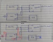
Now my question on the ammeter. I'm struggling to figure out how to wire the ammeter in series with the timer relay and PCB. I can wire the ammeter and PCB to the PS without the timer according to the diagrams below and the coil and ammeter work just fine. But how do I put the ammeter in series with the PCB when I use the timer? Is the handdrawn wiring diagram shown correct? Note: "PCB" in my drawing is the zvs board. It's this one https://www.amazon.com/KOOBOOK-Volt...ld=1&keywords=1000w+zvs&qid=1631834192&sr=8-3
Thanks for any and all help!
View attachment 1280100View attachment 1280101
View attachment 1280107
Probably---
- the power input into the timer is to power the timer only, not a downstream component and can be powered by the 36vdc you are sending through to the ZVS pcb or any other convenient appropriate power source of 5-36vdc (if you have a lower voltage than 36v available in your build, say 12v for fans, that might be better than the 36v you have dedicated to powering the ZVS board).
- the 'output' terminals of the timer are actually a relay, and are not meant to directly power a downstream component - in other words, its just a switch to connect/disconnect the power to the downstream component.
- the 'trigger' terminals are just for connection of a momentary switch to trigger the timers function and don't need any outside power input.
I altered the diagram to show how I would use your existing components, but if you used the timer relay to trigger a larger relay (like your SSR) that would probably be better from a reliability standpoint and less likely to cause problems with the timer circuitry.
Just my two cents...hope it helps. (if you try these changes, I suggest you test with as simple and low a voltage circuit as possible to prevent damage to components before layering it all back on to test the total circuit)
Attachments
Last edited:
I am probably totally wrong, but in my experience with similar components I would make the following observations.
Probably---
- the power input into the timer is to power the timer only, not a downstream component and can be powered by the 36vdc you are sending through to the ZVS pcb or any other convenient appropriate power source of 5-36vdc (if you have a lower voltage than 36v available in your build, say 12v for fans, that might be better than the 36v you have dedicated to powering the ZVS board).
- the 'output' terminals of the timer are actually a relay, and are not meant to directly power a downstream component - in other words, its just a switch to connect/disconnect the power to the downstream component.
- the 'trigger' terminals are just for connection of a momentary switch to trigger the timers function and don't need any outside power input.
I altered the diagram to show how I would use your existing components, but if you used the timer relay to trigger a larger relay (like your SSR) that would probably be better from a reliability standpoint and less likely to cause problems with the timer circuitry.
Just my two cents...hope it helps. (if you try these changes, I suggest you test with as simple and low a voltage circuit as possible to prevent damage to components before layering it all back on to test the total circuit)
Thanks for the advice!
The timer is actually meant to be wired the way I have it in my diagram.
Here's an update.
I got the new timer in, thinking the other was possibly faulty. The new timer does the exact same thing. With only the 33v power going into the timer, it flickers. Even without the zvs wired in. The other one did the same. I had that wrong in my problem description. So this timer is definitely not advertised correctly! On the back of the board it even says 5-30V on the power supply terminals. I'm not sure why the other guys I've seen use it with higher than 30V had it working.
Anyway, I received my 40DD SSR also. I wires the timer up to power it and the SSR switch with 12V. Then wired my VA meter into the relay load circuit.
Works like a charm!!!
I had my Peterson 284win brass (real thick brass like Lapua) start to glow, both neck and shoulders at same time, in 4.8s. I have 8.75 coils of 1/8" copper tubing. The height is 1.330 (outside to outside edge) and the ID is 0.890. The case is positioned to have the case mouth just below the top coil so I can get the shoulders and neck/shoulder junction well annealed without overcooking the neck and mouth. The frequency it should be oscillating at is about 116kHz.
The max current draw it gets up to is about 20A just for a half second. Even though my PS is rated for 16.7A, it doesn't trip. So I'm not sure if my ammeter is off or if it just doesn't stay above 16.7A long enough to trip the PS. Is this going to get my PS if I operate it like this long term?
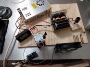
Here's a picture of my horrible quick setup just to verify it works. Next step is to build my enclosure and get it plumbed and wired nicely


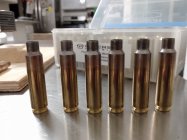
I loaded my first batch of induction annealed cases last night. The seating force was so very consistent! Thank you guys for the help on the SSR info!! I'm really excited to anneal now haha. I just need to make an integrated platform, case guide, and an easy manual trap door solution and I'll be able to rip through hundreds in no time 
One question on the cooling system though.
I just used regular auto antifreeze in mine. I know some propylene glycol has antimicrobial compounds in it to prevent biofilm buildup, but don't know if antifreeze typically has this. Does anyone know if this will be a problem? And is there any corrosion potential in the induction coil or cheapo fan hex with antifreeze?
I just used regular auto antifreeze in mine. I know some propylene glycol has antimicrobial compounds in it to prevent biofilm buildup, but don't know if antifreeze typically has this. Does anyone know if this will be a problem? And is there any corrosion potential in the induction coil or cheapo fan hex with antifreeze?
I am having trouble with the voltage/amperage meter displaying half of what it should be. I know I have read about someone else on this thread having the same problem, and it was solved. But for the life of me I can't find it on the 129 pages.
I have wired it according to Ginas original diagram.
Anyone have any ideas what I am doing wrong?
Many thanks.
You're not doing anything wrong. When they sent you the meter and the shunt, they didn't send the correct pair, i.e. the shunt isn't matched to the meter.
i do 50bmg .the coil is 7 turns and takes 7 or eight seconds.
Similar threads
- Replies
- 74
- Views
- 47,356
- Replies
- 0
- Views
- 1,576
Upgrades & Donations
This Forum's expenses are primarily paid by member contributions. You can upgrade your Forum membership in seconds. Gold and Silver members get unlimited FREE classifieds for one year. Gold members can upload custom avatars.

Click Upgrade Membership Button ABOVE to get Gold or Silver Status.
You can also donate any amount, large or small, with the button below. Include your Forum Name in the PayPal Notes field.
To DONATE by CHECK, or make a recurring donation, CLICK HERE to learn how.

Click Upgrade Membership Button ABOVE to get Gold or Silver Status.
You can also donate any amount, large or small, with the button below. Include your Forum Name in the PayPal Notes field.
To DONATE by CHECK, or make a recurring donation, CLICK HERE to learn how.


