• This Forum is for adults 18 years of age or over. By continuing to use this Forum you are confirming that you are 18 or older. No content shall be viewed by any person under 18 in California.

Induction brass annealer redux

"Nothing to do with accurate shooting." - Gina

Oh, everything is boiling down to the accurate shooting and electronics. As a matter of fact I went back to history. I named my last machine "Tesla-Oakley Annealing".

Thanks Gina & Eric
 
Many on other sites have recommended matching the coil to the total capacitance of the annealer board. It seams that GinaErick arrived at their size by trial and error, but it can also be calculated mathematically. The coil supplied with ZVS boards run at approx. 95KHz. You can calculate the coil frequency using the following formula:

f=1/(2π√(LC)) where C = the total capacitance of the ZVS board in Farads (multiply µF by 0.000001) and

L (in Henrys)=0.000001*(N^2*D^2)/(18D+40l) where N = number of coils, D = 0.5(ID+OD) of coil and l= length of coil (use inches for length and diameter)

By designing your coil to keep the frequency around 95KHz and using the smallest possible inside diameter for your cartridge size, you will increase the efficiency of your annealer so it will run cooler and with less power. Remember that the magnetic field affecting the brass decreases by the inverse cube law (R^-3), so changing the diameter of the coil even a few mm can have a tremendous affect on the energy being transferred to the brass. If you want to focus the energy further, you can decrease the length of the coil by adding a second or third row around the first (as long as they do not touch). Obviously this changes the length and outside diameter of the coil in the formula. I used a double wound coil, 6.5 turns, inside diameter of 0.65 inches. This allowed for better visualization of the case neck by the flame sensor. It will melt my 300 Weatherby cases in under 4 sec and anneal my .223 in around 2 sec.
Can you please elaborate more on the coil and maybe post a picture. I would appreciate it. I am building and want to explore as many options as possible.
thanks Lee
 
Hello to all. I have been reading this thread for the last fun days, wow what a read. Gina, Eric thanks for the original build and all the support over all the time. I was building mine prior to reading this unbelievable amount of information. So I am not on a budget and love to tinker. I got a 48v 600 watt PSU and a 36 volt 1000 watt PSU. I tried the, both with the same case 308 I don’t see much of a difference in the time or power as a matter of fact the 48 volt seems faster. I am running everything else as per the original design. 1000w ZVS 20 amps. I did buy a cheap timer from Amazon and it only has one output so the trap door has not been installed. I ordered the same timer you guys are using. Why would the 1000 watt 36v be slower time to anneal ?
 
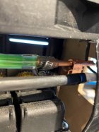
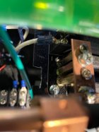
Well might as well get a few more ideas in. I cant stand the idea of all this tech to make this thing and leave in factory stand offs with the clip so for now I just removed the top clip that holds down the pipe and screwed a copper piece then soldered a copper clamp onto it then ran the 1/4 pipe through the clamp. I have a basic understanding of circuits and controls but no real knowledge if electronics, Is there any reason i cant completely eliminate the stand offs and just solder in a heavy gauge wire ?
 
Well might as well get a few more ideas in. I cant stand the idea of all this tech to make this thing and leave in factory stand offs with the clip so for now I just removed the top clip that holds down the pipe and screwed a copper piece then soldered a copper clamp onto it then ran the 1/4 pipe through the clamp. I have a basic understanding of circuits and controls but no real knowledge if electronics, Is there any reason i cant completely eliminate the stand offs and just solder in a heavy gauge wire ?

I didn't solder it in place, but I did try the heavy gauge wire connection between my ZVS board and the coil because that allowed me to adjust the height of the coil independantly of the ZVS board position (only about 6 inch long wires), but the wires themselves became the limiting factor in my cycle rate because of heat build up in the wire.
I am currently redesigning and rebuilding my rig to eliminate the wires and having the height adjustment be in the platform.
 
8 turns it is. and Erick ( screen name Hollywood) did the trial and error work to find the ideal coil size.

Hard to believe it will be coming up on 5 years since the original post on the "GiniaErick" was first posted.
i've been watching in amazement the innovations that have taken place over the years.
From microprocessor controlled annealers to 3 D printed mechanical systems. Sometimes when reading this thread I wonder if I had not accidently wandered onto a "Popular Electronics/Computers website". Nothing to do with accurate shooting.
And then there are the folks like Frank that have built the the original GinaErick and are very happy with it.
It works !!
With a smile on my face, good luck to you all
Gina
I built the original Gina Erick unit and it has been flawless for me. Currently, I’m annealing 6 dasher, 308, 25-06, 6.5CM and 30-06. One odd thing I found was my little 6 Dasher cases take 6.4 sec to anneal and the much larger 6.5CM hornady cases take only 4.1 seconds. It was hard to believe.
dave
 
Hello Dave
I believe it's that the larger cases are closer to the coil. If the coil were wound with a smaller a diameter, the anneal time for the dasher brass wound be shorter. The present size of the coil was chosen for just the very reason of all those different calibers you are annealing.
Gina : }}
 
I can run 50 308 cases through mine nearly as fast as it will go. The board will run nearly continuously if you provide enough heat dissipation. Many people use stick on heatsinks under the capacitors these are a major source of heat as are the inductors and the standoff connections I soldered mine to the board and added some wire to the circuit board traces.
Hi David, can you please explain the placing of heatsinks under the capacitors, or do you have some pics maybe?
 
Hello Dave
I believe it's that the larger cases are closer to the coil. If the coil were wound with a smaller a diameter, the anneal time for the dasher brass wound be shorter. The present size of the coil was chosen for just the very reason of all those different calibers you are annealing.
Gina : }}
Thanks Gina. You rock. Hope you are doing good and fully recovered. Stay off the roof, that’s a kids game. Stick to shooting and electronics project where you really excel.
Dave
 
Thank you :-)) Yea 4 broken ribs and a week in the hospital was not fun. Fully recovered now.
Sounds like you really have a handle on your annealer. adding heat sinks and such.
Way to go.
Gina
 
Thank you :)) Yea 4 broken ribs and a week in the hospital was not fun. Fully recovered now.
Sounds like you really have a handle on your annealer. adding heat sinks and such.
Way to go.
Gina
Thanks Gina, I give 100% to you for convincing me to make a run at this project. I likely wouldn’t have tried it without the numerous conversations we had.
dave
 
Can you please elaborate more on the coil and maybe post a picture. I would appreciate it. I am building and want to explore as many options as possible.
thanks Lee
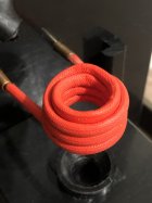
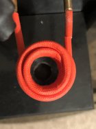
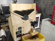
Sorry for the late replay, I was on vacation last week and did not have my annealer with me. The coil is double wound around a .65" tube. The inner winding is 3.5 turns and the outer is 3 turns. The red covering is Uxcell insulation sleeve 3mm I found on Amazon, it is a fiberglass and silicone heat shield used to allow for a tight coil wind without the coils touching each other. Let me know if you have any other questions.
 

Attachments

  • IMG_6180.jpg
    IMG_6180.jpg
    335 KB · Views: 52
  • IMG_6181.jpg
    IMG_6181.jpg
    325.7 KB · Views: 46
  • IMG_6182.jpg
    IMG_6182.jpg
    336.8 KB · Views: 48
Hey everyone,

I am most of the way through building my second annealer as I was silly enough to be talked out of my first by a friend. I have taken the opportunity to include an auto feed on this one.

I am having trouble with the voltage/amperage meter displaying half of what it should be. I know I have read about someone else on this thread having the same problem, and it was solved. But for the life of me I can't find it on the 129 pages.

I am using a 50a shunt Off eBay.

I have wired it according to Ginas original diagram.

Anyone have any ideas what I am doing wrong?

Many thanks.
 

Attachments

  • IMG_20210904_161918356.jpg
    IMG_20210904_161918356.jpg
    304.1 KB · Views: 74
Hi all, it's my first post here. I've been a lurker for quite awhile and decided to join after I started reading this thread. I've started building an annealer and have a couple of questions/problems.

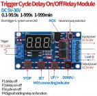
I have a 36v 16.7A PS, a 1000W zvs board, the timer in the picture (36v rated) and a bayite ammeter that has a built in shunt. I'm triggering the timer with a separate 12v circuit. I have the voltage supply on the PS turned down to 33V.

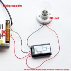
When I wire my induction PCB to the timer, even when I exclude the ammeter, the display will flicker rapidly and it doesn't show anything meaningful. The trigger also won't work to fire up the PCB. But if I remove the load wires from the timer (the PCB) then the timer will work. It seems it's only when I connect the load that it goes bezerk. I have it wired according to the picture below. No shorts or anything. Also, if I just wire the PCB directly to the PS, ammeter in the loop or not, the work coil will do it's job and fry a cartridge case. So, no issue with the induction PCB. Does it sound like a faulty timer relay?
71M2pMZgV0L._AC_SL1500_.jpg

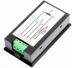
Now my question on the ammeter. I'm struggling to figure out how to wire the ammeter in series with the timer relay and PCB. I can wire the ammeter and PCB to the PS without the timer according to the diagrams below and the coil and ammeter work just fine. But how do I put the ammeter in series with the PCB when I use the timer? Is the handdrawn wiring diagram shown correct? Note: "PCB" in my drawing is the zvs board. It's this one https://www.amazon.com/KOOBOOK-Volt...ld=1&keywords=1000w+zvs&qid=1631834192&sr=8-3

Thanks for any and all help!
61-PujMB6aL._AC_SL1500_.jpg81vC-YGSfCL._AC_SL1500_.jpg
IMG_20210916_135446934.jpg
 
Last edited:
I didn't use that induction board so I'm somewhat at a loss. Does the induction board have a low level ON/OFF input or does it just have a high power IN and OUT? Just guessing but according to your sketch I don't imagine the timer board can handle the high power required for the induction board. If the induction board doesn't have a low power ON/OFF input then the timer output might have to be used to turn on a solid state relay which, in turn, would supply power to the induction board.

The high frequency of the induction board may also be messing with the timer.

Yes the induction board is only high input. The timer switch is rated to 36v and 15A. It says it can do up to 30A with "enhanced heat dissipation". It's this one https://www.amazon.com/5V-36V-Modul...=relay+timer+switch+36v&qid=1631830020&sr=8-3

There have been other annealers made with this type of timer switch, over on snipers hide thread. They didn't seem to have any problem with running 30V and 12-15A directly through it.

I did request a return on that timer and ordered another. So if the next one doesn't work, I may see about using a spst relay with a snubber that's activated off a 12v output timer.

I'll try to wire up the switch to do a 12V output instead of 33v tonight to see if that will work.

Thoughts on the ammeter series wiring?
 
Well I confirmed the timer wasn't advertised correctly. Wiring it with a 12v output and multimeter it worked just fine. So, hopefully the new timer works correctly or I'll get a relay.
 

Upgrades & Donations

This Forum's expenses are primarily paid by member contributions. You can upgrade your Forum membership in seconds. Gold and Silver members get unlimited FREE classifieds for one year. Gold members can upload custom avatars.


Click Upgrade Membership Button ABOVE to get Gold or Silver Status.

You can also donate any amount, large or small, with the button below. Include your Forum Name in the PayPal Notes field.


To DONATE by CHECK, or make a recurring donation, CLICK HERE to learn how.

Forum statistics

Threads
165,291
Messages
2,192,755
Members
78,811
Latest member
Targetmaster77
Back
Top