• This Forum is for adults 18 years of age or over. By continuing to use this Forum you are confirming that you are 18 or older. No content shall be viewed by any person under 18 in California.

Induction brass annealer redux

Thank you very much for this answer. Do you have any pictures of the IR flame sensor positioning if it is not too much to ask? And how you integrated it on your assembly.
I have 2 caliber models to anneal: 222R and 7.08R. But I use several brands in these calibers: Winchester, Lapua, Norma and Sako. Do you think it would work for variations of calibers and brands with the same IR flame sensor setting?

But then we come back to the point of what method gives the correct neck anneal? The emerging cherry red? Or a little more?
 
How much variance in time and joules do you see if you use the flame sensor with close to identical brass, same caliber, make and lot? The flame sensor seems to use a pot to set the temperature to trigger on. So using the flame sensor the trick is adjusting the pot to the right value of heat and hopefully that setting applies to other types of cases well. The older method requires the user to test time settings to get the "right" value for a specific lot of cases.
I don't have a large sample of cases to gather data from. My 5.56 cases are mixed head stamps and vary considerably in the time and energy (Joules) required to make them just start to glow. I have done 30 or so 300 Weatherby cases, all Remington head stamps and they don't vary by more that 5 hundredths of a second or by more than about 75 Joules.

The particular sensor that I used has an adjustable pot that is used in conjunction with the analog output of the sensor, and the sensitivity is adjustable this way. In addition, the sensor has a digital output between 0-1023 (1023 = no light, 0 = full light). The pot adjustment has no effect on the digital output, only on the analog output. The amount of light and the distance to the light both affect the digital output, as does any ambient light in the specified spectrum. For my set up, I used the digital output (this way I could adjust the sensitivity through the Arduino and not have to mess with adjusting the pot) and found a value of 50 to work at the distance my sensor is mounted from the case neck.
 
Last edited:
Thank you very much for this answer. Do you have any pictures of the IR flame sensor positioning if it is not too much to ask? And how you integrated it on your assembly.
I have 2 caliber models to anneal: 222R and 7.08R. But I use several brands in these calibers: Winchester, Lapua, Norma and Sako. Do you think it would work for variations of calibers and brands with the same IR flame sensor setting?

But then we come back to the point of what method gives the correct neck anneal? The emerging cherry red? Or a little more?
Annealing brass is a function of temperature and time. The 700 degrees Fahrenheit that is often propagated among reloaders as the proper brass annealing temperature actually needs to be maintained for 1 hour to anneal brass. The following formula is used to calculate the time and temp to anneal brass:

B=1.38065x10^-23 (Boltzmann constant)
E=0.327x10^-18 (constant for the material, in this case brass)
T1 in Kelvin = 644 (700 F)
t1 in sec = 3600 (1hour)
T2 in Kelvin = target temp
t2 in sec = time to anneal

t2=t1*exp^(-E/B*(1/T1 - 1/T2))

This is easy to plug into Excel and if you pick 810.9 K (1000 F) for your target temp you will anneal in 1.88 seconds. Note that brass starts to glow between 950 F and 1050 F depending on the exact composition. Using 900 F changes the required time to 16.1 seconds.

I am currently annealing .223/5.56 cases (mixed head stamps) and 300 Weatherby case (all Rem head stamps). Both anneal perfectly using the same "glow" setting so I think it will work for your cases as well.

My flame sensor is 1.15 inches from the case neck.
 

Attachments

  • IMG_5952.jpg
    IMG_5952.jpg
    383.9 KB · Views: 146
I don't have a large sample of cases to gather data from. My 5.56 cases are mixed head stamps and vary considerably in the time and energy (Joules) required to make them just start to glow. I have done 30 or so 300 Weatherby cases, all Remington head stamps and they don't vary by more that 5 hundredths of a second or by more than about 75 Joules.

The particular sensor that I used has an adjustable pot that is used in conjunction with the analog output of the sensor, and the sensitivity is adjustable this way. In addition, the sensor has a digital output between 0-1023 (1023 = no light, 0 = full light). The pot adjustment has no effect on the digital output, only on the analog output. The amount of light and the distance to the light both affect the digital output, as does any ambient light in the specified spectrum. For my set up, I used the digital output (this way I could adjust the sensitivity through the Arduino and not have to mess with adjusting the pot) and found a value of 50 to work at the distance my sensor is mounted from the case neck.
I had given up on the IR sensor thinking that it overheated the brass (I tried the same setup with the adjustable pot version). I could only get it to trigger when the brass was glowing which is the spectrum it can detect. I was doing thinner brass like 30-30, 303SAV, etc., which can cook quickly. Also do the heavier 30-06 variants like 300SAV, 250SAV, 257 Roberts, etc. I will admit that I did not get the "anneal color band" when I was just below the glowing point (adjusting the time just below where the brass would start to glow with the lights out). I've also used different temperature grades of Tempilaq to test.

Is the thinking now that we do need to get the temperature higher to get a proper anneal?

Anther issue that I ran into in measuring Joules was the speed of the analog inputs. They are actually fast but when switching channels to the A/D converter you can run into issues if you read too quickly and not giving time for "discharge". Just be aware that some sensors don't draw that much load and can cause issues to where the A/D converter will start giving wrong values.
 
When estimating joules of energy, am I correct that you are measuring the input voltage and current and assuming a relationship to the induction coil current and energy heating the brass? It is safe to say the more input joules the more net induction current and more actual heating of the brass, but the actual energy going into heating the brass is likely not a simply linear relationship.

e.g. When nothing is inside the heating coil the current isn't zero but the heating is. So a simplistic model may subtract out the minimum joules when nothing is inside the coil and make some guesses about what percentage of joules above that amount is really going into the brass.

BTW the feeder design looks great. Too bad I don't own a 3d printer.
 
Hello to all,

Another Frenchman from France sharing his work with you.
I wanted to thank all the participants of this topic and especially @Gina1 for having created this thread. Thanks also to @KeeWay for sharing files for the Arduino and Nextion code.

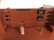
So I present you my first works on my machine which is in its second version:


On the other hand I have many questions about the annealing time and how to proceed. I really liked the scientific approach of @Patrice COTTES, your results were very interesting.
I'm not too much for the Tempilak method, I find it quite empirical, I'm satisfied for the moment to get the red emerging on the top of the neck.
I also like the system with the IR detector of @VenatusDominus . I have a question about this, what does this sensor detect? I could eventually implement it in my Arduino program to test it but it will require quite a bit of analysis of the KeeWay program.

In the meantime thank you very much for all your experience sharing, and I stay tuned to this thread and I could also help those who want to debug the Arduino program I use.
Really impressive! Well done!
 
I've been doing quite a bit of testing of my case feeder and dropper setups and have them to the point where I'm happy with the way it's all working. I've uploaded the latest version to Thingiverse today if anyone wants to print the parts themselves:
https://www.thingiverse.com/thing:4902058
https://www.thingiverse.com/thing:4916236

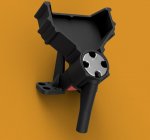
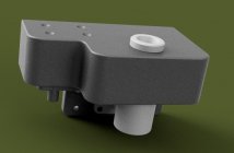
Some renderings of both parts below:

View attachment 1269231
View attachment 1269232
View attachment 1269233
Hi Greg
Can you please share info regarding the solenoid used in the dropper.
Job well done Mark and Greg
 
I have both, PLC and ARDUINO controlled annealing machines. It would be "grand plaisir" to send you the codes, provided you publish yours .308 annealing results.

Merci
Thanks
I didn't have enough time for testing my annealer on .308 cases. As soon as it will be done, you'll get the results. For now, impossible, it's summer vacations.
Regards
Patrice
 
Sorry I see the info was already supplied
The solenoid only has a short throw but I've adjusted the ratio on the lever so it pulls far enough to clear the drop port. It's very simple but works really well and it's a cheap part to source.

I had a few people comment that the feeder hopper was a little small as well. I've done a bit of a redesign to add some capacity while still fitting the bed of an average sized printer. It hold quite a few more cases. I've updated the files on Thingiverse, it's only the tray and surround that's changed, the rest is the same.
 
Thanks
I didn't have enough time for testing my annealer on .308 cases. As soon as it will be done, you'll get the results. For now, impossible, it's summer vacations.
Regards
Patrice
Bonjour !

Patrice,

Here is my code. The code is very basic C, learnt from this forum and some other Arduino forums. I'm a Professional Engineer (Marine and Electrical) and not a programmer. So, it would be very easy to understand the not so sophisticated code.

Some details in my built:
- 3 step motors (two for lifting the case plate and one to move out the annealed case - I use ferrite core).
- 3 relays (Start/Stop the power supply, transfer power between the step motors, and one energizing the ZVS board)
- 2 selector switches (one for Test, One Shot, Auto (cycling), and one for moving up and down the case plate)

That's it

Bonne Chance :)

`
Code:
// Power
   int PB_OnOff = 34;  // Power PB
   int PwrON    = 35;   // Power LED
// Annealing
   int PB_Annl  = 36; // Annealing PB  
   int PwrAN    = 37;   // Annealing LED
// Mode Sel  Switch  
   int PinONE =  30;  // Sel Switch - TEST, ONE, AUTO
   int PinAUTO = 31;  // Sel Switch - TEST, ONE, AUTO   
// Lift Sel Switch
   int PinDN = 32;    // Sel Switch Lift DN
   int PinUP = 33;    // Sel Switch Lift UP
// Traffic Lights
   int PinGRN = 38;   //   Green
   int PinYLO = 39;   //   Yelow
// Relays
   int PwrR1 = 46;    // Relay 1 Power Supply
   int StepR = 47;    // Relay 1 Step power select
   int PwrR2 = 48;    // Relay Anneal
// Analog reading
   int PinV = A1;     // Volts
   int PinA = A2;     // Amps
   int PinIR = A3;    // IR Sensor

// FUNCTIONS Declaration
   void DropGate();
   void SelSwitch();
   void StartStop();
   void TheLift(boolean Up);
   void Anneal();
   void BillBoard(int N);
   void AnnSwitch(boolean ON);
   void TempKeep();
   boolean E_Stop();

// == GLOBAL VARABLES ==
   boolean SysIni = true;
   int Task = 0;
   int AnnTime = 0;
   int AnnCount = 0;
   int SelSw = 0;
   int Lvl = 0;
   int T = 0;
   int Steps = 585*2; //////int Steps = 200;
   int Level[] = {18, 24, 30}; int LvlN = 3; // .284, .260, 6 mm  

// Step Motor Library
   #include <Stepper.h>
   Stepper Lift(Steps, 8,10,9,11);
   Stepper Gate(Steps, 8,10,9,11);
// Screen Display library
   #include <LiquidCrystal_I2C.h>
   #include <Wire.h>
   #include <EEPROM.h>
   LiquidCrystal_I2C lcd = LiquidCrystal_I2C(0x27, 20, 4); 

// =============
// === setup ===
// =============
   void setup() {
// Serial Port
   Serial.begin(115200); 
// Initiate the LCD:
    lcd.init(); lcd.backlight(); 
// Initialize Memory
    Lvl = EEPROM.read(10);
// EEPROM.write(10, 10); establishing reference level - one time only    
  
// Start, Stop, Annealing
     pinMode(PB_OnOff,INPUT_PULLUP); digitalWrite(PB_OnOff,HIGH); // Start/Stop Push Button
     pinMode(PB_Annl, INPUT_PULLUP); digitalWrite(PB_Annl, HIGH); // Annealing Push Button   
// Power Supply and Annealing - LED, Relays
     pinMode(PwrON, OUTPUT);  digitalWrite(PwrON, LOW);           // ON/OFF LED    / Relay 1
     pinMode(PwrAN, OUTPUT); digitalWrite(PwrAN, LOW);            // Annealing LED / Relay 2 
// Selector Switches
     pinMode(PinONE,  INPUT); digitalWrite(PinONE,  HIGH);   // Sel Switch - TEST, ONE, AUTO
     pinMode(PinAUTO, INPUT); digitalWrite(PinAUTO, HIGH);   // Sel Switch - TEST, ONE, AUTO
     pinMode(PinUP, INPUT_PULLUP); digitalWrite(PinUP, HIGH); // Sel Switch Lift UP
     pinMode(PinDN, INPUT_PULLUP); digitalWrite(PinDN, HIGH); // Sel Switch Lift UP    
// Traffic signals
     pinMode(PinGRN, OUTPUT); digitalWrite(PinGRN, LOW);      // Trafic Signal Green
     pinMode(PinYLO, OUTPUT); digitalWrite(PinYLO, LOW);      // Trafic Signal Green
// Pwr Relays
     pinMode(PwrR1, OUTPUT); digitalWrite(PwrR1, HIGH);     // On/Off 
     pinMode(PwrR2, OUTPUT); digitalWrite(PwrR2, LOW);      // Anneal
     pinMode(StepR, OUTPUT); digitalWrite(StepR, HIGH);     // Step Motor Pwr Select
// Step Motors
     Lift.setSpeed(35); Gate.setSpeed(30);
}

// =================
// === Main Loop ===
// =================
   void loop() {
// Inititializing 
   if (SysIni == true){
      SysIni = false; // On Time execution
      if (digitalRead(PinONE) == HIGH && digitalRead(PinAUTO) == LOW) {SelSw = 1;}  // TEST
      if (digitalRead(PinONE) == LOW  && digitalRead(PinAUTO) == LOW) {SelSw = 2;}  // ONES
      if (digitalRead(PinONE) == LOW  && digitalRead(PinAUTO) == HIGH){SelSw = 3;}  // AUTO  
      int N = 0;      
      for (N = 0; N <= 3; N++){
         BillBoard(N); SysIni = false;
      }
   }   
// Volts
    BillBoard(3);
// Task Assignment
   if (digitalRead(PB_OnOff) == LOW) // Strat Stop
      {Task = 1;}
  if (digitalRead(PB_Annl) == LOW)   // Annealing
      {Task = 2;}
   if (digitalRead(PinUP) == LOW)    // Cartridge Lift Up
      {Task = 3;}
   if (digitalRead(PinDN) == LOW)    // Cartridge Lift Dn
      {Task = 4;}
// Monitor SelSw  
    SelSwitch();   // monotors TEST, ONE, AUTO Sel Sw.                                              
// Do the Task
   switch (Task){
     case (1):  StartStop()  ; Task = 0; delay(250); break;
     case (2):  Anneal()     ; Task = 0; delay(250); break;
     case (3):  TheLift(true); Task = 0; delay(10); break;
     case (4):  TheLift(false); Task = 0; delay(10); break;
   }
   for (int y = 8; y <= 11; ++y){digitalWrite(y, LOW);}  // Deenergize the step motors    
}


// ================
// ==== Anneal ====
// ================
   void Anneal(){
   int y=0; boolean InList=false;
// Anneal Time
   BillBoard(1);                   // AUTO, ONESHOT
   if (SelSw == 1) {AnnTime=6500;} // TEST
   if (digitalRead(PwrON)==false)  // No Power
      {AnnTime = 0;}
// The LED and the Anneal Relay
   AnnSwitch(true); 
// Start Annealing 
   int bTime = millis(); int cTime = 0;                                
   while (cTime<AnnTime){
      cTime = millis()-bTime; T = cTime;    
      delay(100); BillBoard(3);                // Show Count Down Time        
      if (E_Stop() == true){return;}           // Interrupt Annealing
   }
// Stop Annealing
   AnnSwitch(false); DropGate();         
   ++AnnCount; BillBoard(2);
// Traffic Signals
    if (SelSw == 3){ // AUTO     
       digitalWrite(PinGRN, HIGH); cTime = 0; bTime = millis();
       while (cTime<2000){                 // Green Traffic
         cTime = millis()-bTime;
         if (E_Stop() == true){return;}    // Stop Annealing                    
       }
       digitalWrite(PinGRN, LOW); cTime = 0; bTime = millis();
       BillBoard(2);       
       while (cTime<2000){                 // Green Traffic
         cTime = millis()-bTime;
         if (E_Stop() == true){return;}    // Stop Annealing
         digitalWrite(PinYLO, HIGH); delay(250);
         if (E_Stop() == true){return;}    // Stop Annealing
         digitalWrite(PinYLO, LOW);   delay(250);
                   
       }               
       Anneal(); // Anneal Again  on AUTO
    }
} 

// =================
// === BillBoard ===
// =================
   void BillBoard(int N) {
// Line 1 - "Tesla Oakley Annealing"
// Line 2 - Set Selected caliber or Level
// Line 3 - TEST, ONES, AUTO, COUNTS
// Line 4 - VOLTS, AMPS, TIMING

// Line 1 Variables
   String sLvl = ""; int sVolt = 0; int sTime = 0; int y = 0; int S = 0;  
// Line 2 Variables
   String sMode = ""; boolean inList = false;
   Lvl = EEPROM.read(10);  
// Line 3 Variables
   int V = 0; int A = 0;
// Is it on The List
   for (y = 0; y < LvlN; ++y){                   
       if (Level[y] == Lvl){inList = true; S = y; break;}
   }

   lcd.setCursor(0,N);
   switch (N){
      case 0:
           lcd.print("Tesla Oakley Anneal"); break;
      case 1:
           AnnTime = 0;                             
           if (inList == true && SelSw != 1){     
              switch (S){
                  case 0: sLvl = ".284 "; sVolt = 46; sTime = 3600; break;
                  case 1: sLvl = ".260 "; sVolt = 46; sTime = 4400; break;
                  case 2: sLvl = "6 mm "; sVolt = 40; sTime = 3800; break;
               }
               AnnTime = sTime;                     
               lcd.print("Set: ");    
               lcd.print(sLvl);lcd.print(sVolt);lcd.print(" V ");
               lcd.print(AnnTime/1000.0,1); lcd.print("s ");                
           }           
            if (inList == false || SelSw == 1){
               lcd.print("Level "); lcd.print(Lvl); lcd.print("      ");
               lcd.print(AnnTime/1000.0,1); lcd.print("s ");
           }
           break;
      case 2: // Line 2       
           switch (SelSw){
                case 1:  sMode = "TEST "; AnnTime = 5000;
                         break;                                              
                case 2:  sMode = "ONES ";
                         if (inList == false){AnnTime = 0;}break;
                case 3:  sMode = "AUTO ";
                         if (inList == false){AnnTime = 0;} break;        
           }                    
           lcd.print("Mode: ");  lcd.print(sMode);
           lcd.print("Cnt "); lcd.print(AnnCount);
           break;                  
      case 3: // Line 3     
           V = 50.0*analogRead(PinV)/1023.0;    
           A = analogRead(PinA)-527; A = - 50*A/1023;
           if(abs(V)<1){V=0;} 
           if (abs(A)<1) {A=0;}      
           lcd.print("Annl: "); 
           lcd.print(V);lcd.print(" V ");
           lcd.print(A);lcd.print(" A ");
           lcd.print(T/1000.0,1);lcd.print("s");
           break;
      }
   }


// ===============
// === TheLift ===
// ===============
   void TheLift(boolean Up) {
      int y = 0;
   // Obey Travel Limits or Pause at Next Cartridge Level 
      while (digitalRead(PinUP) == LOW || digitalRead(PinDN) == LOW){     
         if (Up == false && Lvl == 10){return;}
      // Is it in the list?     
         for (y = 0; y < LvlN; ++y){
            if(Level[y] == Lvl)
              {BillBoard(1); delay(1000);break;}
         }
      // Spin it
          digitalWrite(StepR, LOW);       
         if (Up == true) {Lift.step( Steps); ++Lvl;}      
         if (Up == false){Lift.step(-Steps); --Lvl;}
         EEPROM.write(10, Lvl); BillBoard(1);                               
      }
      digitalWrite(StepR, HIGH);
   }               

// ====================
// ==== DROP_GATE =====
// ====================
   void DropGate(){
    int y; int Move = 227; // 15 degree Gate.setSpeed(30); Lift.setSpeed(35);
    Gate.step(-Move); delay(1250);
    Gate.step(Move);  ;                  
    for(y = 8; y<=11; ++y){digitalWrite(y, LOW);}                 
    }

// =============
// == E-Stop ===
// =============
   boolean E_Stop() {
   boolean STOP = false;
   boolean AnnON = false;
      if (digitalRead(PwrR2)==HIGH)
         {AnnON = true;}
      if (digitalRead(PB_OnOff) == LOW) {
         AnnSwitch(false); // Stop Annealing
         if (AnnON == true)
            {DropGate();}
         digitalWrite(PinGRN, LOW);
         digitalWrite(PinYLO, LOW);
         STOP = true;
      }      
      return STOP;        
   }


//====================
//==== START_STOP ====
//===================
  void StartStop(){   
  if (digitalRead(PwrON)==LOW)
     {digitalWrite(PwrON, HIGH);digitalWrite(PwrR1,LOW);return;}
  if (digitalRead(PwrON)==HIGH)
     {digitalWrite(PwrON, LOW);digitalWrite(PwrR1,HIGH); return;}            
  }

//====================
//==== SelSwitch ====
//===================
  void SelSwitch(){
   int S = 0;
   if (digitalRead(PinONE) == HIGH && digitalRead(PinAUTO) == LOW)  {S = 1;}  // TEST
   if (digitalRead(PinONE) == HIGH  && digitalRead(PinAUTO) == HIGH){S = 2;}  // ONES
   if (digitalRead(PinONE) == LOW  && digitalRead(PinAUTO) == HIGH) {S = 3;}  // AUTO
   if (digitalRead(PwrON)  == HIGH){BillBoard(3);} // Show Volatage all the time
   if(SelSw == S)
     {return;}
   if(SelSw != S)
     {SelSw = S; AnnCount = 0; BillBoard(1);BillBoard(2);}    
  }

// =================
// === AnnSwitch ===
// =================
   void AnnSwitch(boolean ON){
      if (ON == true){
         digitalWrite(PwrAN, HIGH); digitalWrite(PwrR2, HIGH); // Contactor and LED ON    
      }
      if (ON == false){
         digitalWrite(PwrAN, LOW); digitalWrite(PwrR2, LOW); // Contactor and LED OFF
      }
   }
 
Last edited:
Hi oliverpsmile,
Thanks for posting your code.

If you can edit your post, you should wrap it in CODE tags.

[ CODE ]
some code goes here
[ / CODE ]

Just take out the spaces in my example above
and it looks like this

Code:
some code goes here
 
Looking to build my own GinaErick and curious about two things:

1. Is there any calculations or guidance on the coil diameter/turns anyone can share or is it "try different sizes and see what works?" Looking at doing 223, 22-250, 308, 35Rem, 6.5CM and 300NM.

2. Considering the cases above, is the standard 48V/12.5A power supply enough or should I look at one of the larger 20A versions?
1. Stick with the original design of 7 turns and 1 1/8 inches diameter. It works for me across a wide range of cases.
2. I recommend the 800W model power supply. It is significantly faster than the original 600W that I started with. I think 12.5W will see you with quite long anneal times, which allows a lot of heat to move into the body of the case, which you want to avoid.
 
I just finished building my own GinaErick annealer with 600watt power supply prescribed in original design and it works great. I think higher wattage will just run up your budget.
Also agree to use 1-1/8 diameter coil (form it around 3/4-inch schedule 40 pvc pipe). I actually count 8 coils in mine but I suppose definition of full coils is subjective - important thing is to match Gina’s original coil picture. I suspect that Gina came up with this coil experimentally rather than calculated - but it will be interesting to see what she has to say. I think this coil will work fine for all your brasses as long as you adjust elevations for each brass.
good luck to you!
 
Last edited:
Looking to build my own GinaErick and curious about two things:

1. Is there any calculations or guidance on the coil diameter/turns anyone can share or is it "try different sizes and see what works?" Looking at doing 223, 22-250, 308, 35Rem, 6.5CM and 300NM.

2. Considering the cases above, is the standard 48V/12.5A power supply enough or should I look at one of the larger 20A versions?
Many on other sites have recommended matching the coil to the total capacitance of the annealer board. It seams that GinaErick arrived at their size by trial and error, but it can also be calculated mathematically. The coil supplied with ZVS boards run at approx. 95KHz. You can calculate the coil frequency using the following formula:

f=1/(2π√(LC)) where C = the total capacitance of the ZVS board in Farads (multiply µF by 0.000001) and

L (in Henrys)=0.000001*(N^2*D^2)/(18D+40l) where N = number of coils, D = 0.5(ID+OD) of coil and l= length of coil (use inches for length and diameter)

By designing your coil to keep the frequency around 95KHz and using the smallest possible inside diameter for your cartridge size, you will increase the efficiency of your annealer so it will run cooler and with less power. Remember that the magnetic field affecting the brass decreases by the inverse cube law (R^-3), so changing the diameter of the coil even a few mm can have a tremendous affect on the energy being transferred to the brass. If you want to focus the energy further, you can decrease the length of the coil by adding a second or third row around the first (as long as they do not touch). Obviously this changes the length and outside diameter of the coil in the formula. I used a double wound coil, 6.5 turns, inside diameter of 0.65 inches. This allowed for better visualization of the case neck by the flame sensor. It will melt my 300 Weatherby cases in under 4 sec and anneal my .223 in around 2 sec.
 
8 turns it is. and Erick ( screen name Hollywood) did the trial and error work to find the ideal coil size.

Hard to believe it will be coming up on 5 years since the original post on the "GiniaErick" was first posted.
i've been watching in amazement the innovations that have taken place over the years.
From microprocessor controlled annealers to 3 D printed mechanical systems. Sometimes when reading this thread I wonder if I had not accidently wandered onto a "Popular Electronics/Computers website". Nothing to do with accurate shooting.
And then there are the folks like Frank that have built the the original GinaErick and are very happy with it.
It works !!
With a smile on my face, good luck to you all
Gina
 
Last edited:

Upgrades & Donations

This Forum's expenses are primarily paid by member contributions. You can upgrade your Forum membership in seconds. Gold and Silver members get unlimited FREE classifieds for one year. Gold members can upload custom avatars.


Click Upgrade Membership Button ABOVE to get Gold or Silver Status.

You can also donate any amount, large or small, with the button below. Include your Forum Name in the PayPal Notes field.


To DONATE by CHECK, or make a recurring donation, CLICK HERE to learn how.

Forum statistics

Threads
165,332
Messages
2,193,471
Members
78,832
Latest member
baconbag
Back
Top