Follow along with the video below to see how to install our site as a web app on your home screen.
Note: This feature may not be available in some browsers.
This Forum is for adults 18 years of age or over. By continuing to use this Forum you are confirming that you are 18 or older. No content shall be viewed by any person under 18 in California.
Found an issue going from alpha/boilerplate/spaghettiwire so it can get changed easy to the finished product- lost current control, acted goofy.
The RSP-750-48 PS manual wants you to reference (provide a 0v) the control voltage to pin 11 (gnd), this results in no workee correctly. With the 0v removed it works exactly as it should. So, control voltage to pin 5 and/or 7 only, no 0v ref on pin 10 or 11. I will change the diagram a few pages back and put a big note in. Sorta weird as I thought I had a solid 0v ref on pin 11, but I guess not. Now its back to absolute rock solid current control. Maybe this weekend I'll do a video and show control input voltage, what PS current and voltage that results in without a case, and with a case. Current stays where you set it, voltage varies.
Well doesn't look like I am allowed to edit the post a page back with the wiring diagrams, the 'bad' one has been deleted, here's the corrected one-
Perfect timing as I'm getting ready to wire in my 5k pot for current control. My version uses an ACE PLC for hopper and release gate solenoids. I've never used this brand of PLC before but it's cheap and small; better option than the larger AB/Micrologix PLCs I've used in the controls industry. Still waiting for my 1/8" copper tubing to arrive, then I can build the hopper and release stations for front panel mounting.
Just a quick note- if the RSP-750-48 PS pulls down below about 5v it goes into fault and requires a on/off reset, so set current limit accordingly for each individual workpiece to operate above that. I would imagine the other models are very similar in protection schemes. Also the OPB716/718Z needs to be about 1/4"-3/8" from object, and a light colored tube (white or opaque white) works best, the dark grey PVC tube in my boilerplate tests isn't optimal by any means and isn't 100% reliable triggering, I think the background color it references is not right. The OPB100Z start switch with power resistors/config in drawing has been 100% reliable. Case feeding isn't a must by any means, more like a "because we can" feature.
Just a quick note- if the RSP-750-48 PS pulls down below about 5v it goes into fault and requires a on/off reset, so set current limit accordingly for each individual workpiece to operate above that. I would imagine the other models are very similar in protection schemes. Also the OPB716/718Z needs to be about 1/4"-3/8" from object, and a light colored tube (white or opaque white) works best, the dark grey PVC tube in my boilerplate tests isn't optimal by any means and isn't 100% reliable triggering, I think the background color it references is not right. The OPB100Z start switch with power resistors/config in drawing has been 100% reliable. Case feeding isn't a must by any means, more like a "because we can" feature.
Good to know on both points! I think I'll go with two of the OPB100Z's as I've tested it on a breadboard and it works well for input to my PLC with a 2.2k pull up resistor. I'll be resetting the timers with my PLC output rather than paralleling across the start/stop switches. In theory anyway lol!
Good to know on both points! I think I'll go with two of the OPB100Z's as I've tested it on a breadboard and it works well for input to my PLC with a 2.2k pull up resistor. I'll be resetting the timers with my PLC output rather than paralleling across the start/stop switches. In theory anyway lol!
Yeah I think two of the 100Z's are better, no cornfusion with background reflectivity. BTW a few pages back there's a diagram on the 100Z breadboard test component values, can run off 12v just fine with a change to the LED power resistor value to keep it under 100mA. From memory its 39R for 5v and 120R for 12v.
The current limit pot certainly works OK, what you'll need to do since the adjustment is pretty much infinite between min and max is put a test workpiece in the coil like a brass rod to reach your current limit and set the current limit to the same value used previously, then start on cases. With a discrete resistor switch this step isn't needed as it returns an exact current value with every switch position. But to be honest 0.1A probably isn't going to make much difference. If I were to make changes I'd include a couple lower current limit steps so small cases have longer anneal times, like all the way down to 7A, just above the PS lower fault limit of ~6.0A.
In your dwg the 5K pot with the 10K pulldown (and a 6K parallel load inside the PS) should result in a lower limit of ~2.15v which should keep it out of fault (below 2.0v), and this should be about 6.5A-6.7A. The response isn't quite linear but pretty close.
Above there are comments about using 1000 uF capacitors.
Be very careful!!
If you put a capacitor accross relay contacts, you may be hastening the arcing problem. When the contacts are open, the capacitor will charge to the voltage across the contacts. When the contacts close, you are putting a dead short (the relay closed contacts) and a very large current will flow thru the contacts to dis-charge the capacitor!
Another pit fall is putting a large capacitor across your DC power supply. This supply probably has a current limit built in. If you put a big capacitor across this supply, say 1000 uF, when a fault occurs, the current will NOT be limited till the 1000 uF capacitor discharges! If your supply is limited at 20 Amps as an example and puts out 60 volts, if a fault occurs such as the oscillator not starting up correctly, a huge current spike may flow in one or both transistors instantly vaporizing them. A well designed power supply needs no capacitor on its output as the supply will have excellent regulation negating the need for external capacitors.
A properly selected relay is designed to switch a rated load current at its rated voltage. This current should be greater than the power supply current rating. Putting a capacitor across the relay contacts can exceed the rated current by an order of magnitude at least! As can placing a capacitor from either relay contact to ground!
Thanks for the warning, but now I still don't know what to do...
My power supply has no build in over protection or something since it's build
from 2 microwave transformers with rewound secondary's.
As protection I have a 15a fuse on the 120vac going into the transformers and a 20a fuse on the 40vdc after the bridge rectifier.
So I have the small diode (1n4007) wired in to protect the 12vdc coil side of relay and am now wondering if a
large diode for the 40vdc side would also work instead of the capacitor? (just like the low voltage relay side and trap door solenoid protection)
By the way, the 80a automotive relays did finally arrive today so I will give one of those a try once I have figured out what to do with wiring in a capacitor or not..
Hope you electronics experts can help.
You shouldn't need any extra component on the coil of the relay. Most 12v automotive relays are already resistor suppressed, a few will have diode suppression.
Its the coils with higher turn counts like solenoids that can produce a lot of flyback, idle air control solenoids, cam control or trans hydraulic control, etc. Relay coils are usually not an issue.
Thanks for the warning, but now I still don't know what to do...
My power supply has no build in over protection or something since it's build
from 2 microwave transformers with rewound secondary's.
As protection I have a 15a fuse on the 120vac going into the transformers and a 20a fuse on the 40vdc after the bridge rectifier.
So I have the small diode (1n4007) wired in to protect the 12vdc coil side of relay and am now wondering if a
large diode for the 40vdc side would also work instead of the capacitor? (just like the low voltage relay side and trap door solenoid protection)
By the way, the 80a automotive relays did finally arrive today so I will give one of those a try once I have figured out what to do with wiring in a capacitor or not..
Hope you electronics experts can help.
In my response a few posts above, I wrote about the possibility of having a welded contact due to the discharge of the capacitor.
Anyway, from my experience, it is more important the gap in the contact rather than the capacitor.
The basic idea is to prevent the spark to keep on going when the relay goes to the N.O. position.
I am finally using a modified 40A relay, just by increasing the gap in the contacts. If you have a 80A relay, I asume that the gap problem is already solved from the factory.
I opened up the 80a and actually the gap was pretty much the same as the 40a one (about 1 millimeter)
So I bended over the NC contact and doubled the gap.
Did a quick test of the relay and the coil is still strong enough to close the circuit with the wider gap.
So I'll put it in and just skip the capacitor.
Good idea! I'm sure you won't have any problem.
Anyway, keep it open and don't replace the cover until you see it working a few cycles in a normal sequence.
Just to be on the safe side.
It isn't just the gap distance that determines voltage level the unit is capable of making/breaking for thousands of cycles reliably, its also very dependent on the contact material. Cheeseball junky no-name units will not use the more expensive or more appropriate material in the contacts.
It isn't just the gap distance that determines voltage level the unit is capable of making/breaking for thousands of cycles reliably, its also very dependent on the contact material. Cheeseball junky no-name units will not use the more expensive or more appropriate material in the contacts.
If the relay craps out way too fast i will replace it with a better one down the road. I got 2 spares also since i ordered 3 of the 80a relays. (Only paid less than 6 USD for all 3 of them )
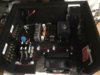
Finally plumbed in the cooling system and coil. After battling a couple leaks and vapor locks, it seems to circulate coolant. I still have some air in the line; any suggestions on bleeding it without getting fluid everywhere?
Working on a prototype release station now and hope to begin programming my PLC to control the solenoids and reset the timers as soon as I get it all wired in.
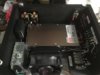
The coolant reservoir should be the highest point in the loop (and by the looks of it is).
If so bleeding should be easy to do with the screw cap on the top of the coolant container.
If it is highest point in the loop then you also don't need the coolant to be filled all the way to the top.
Any air should be getting pushed out / through the lines and radiator by the pump and will stay in the reservoir because it is the highest point.
WOW...... That is looking so nice !!. As bertn said the pump tank is the highest part of you cooling system, so all air should work it's way up and out. Is your radiator vertical ?
I did have a problem with air in the coolant lines on the first build (mod1) Because of space limitations I had it mounted sideways. Thought it would make no difference but I always had some air in the line. The newer unit (rev2) it was mounted vertical and have not seen an air bubble in that one since it self purged.
Gina
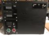
My radiator is vertical and the tank is the highest point. I'm pretty sure all the air will eventually work its way out. Here's a shot from the back that better shows the elevation.
Thanks Kit-808...Good to know. I noticed I could get the air pockets to shift around a bit by tilting the case; guess I need to be more agressive and rotate it in all different orientations to get the air to the reservoir.
This Forum's expenses are primarily paid by member contributions. You can upgrade your Forum membership in seconds. Gold and Silver members get unlimited FREE classifieds for one year. Gold members can upload custom avatars.
This site uses cookies to help personalise content, tailor your experience and to keep you logged in if you register.
By continuing to use this site, you are consenting to our use of cookies.
")


") )
)