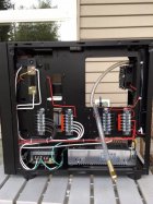
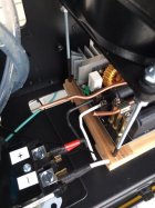
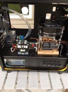
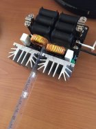
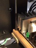
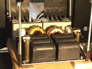
Once energized without a connected coil - the board is gone. Lesson learned the hard ($$$) way. In the above postings - the power supply is OK.The boards need the coil to be attached to work.
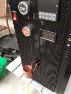
If you mean a multi meter, yes I do. As for soldering skills, in my humble estimation, terrible.NearZero - I feel your pain! Being a (retired) test engineer (electronic) I've been through numerous situations debugging problems. Maybe that's why I don't have as much hair as I used to. A lot of times when you find the problem the response is DUH, why didn't I see that before? Software too, although software only does what you tell it to do. Even though you swear you're not telling it to do anything wrong.
Do you have an ohm meter? How are your soldering skills?
The wire going into the Contactor are + & - from 48V power supply and a smaller black wire to the V/A meter display. Wires going out of the Contactor are + & - 48V to the induction board. The other two wires are for the annealing LED indicator light. The black wire in the front of the contactor lead to the Sestos Timer and the light green wire is a ground wire.Maybe it just me...but there look like there are entirely too many wires going into that relay. Mine only has 6...48V +/- IN, 48V +/- OUT, and 12V +/- (controlled by the timer) to power the relay closed.
Also, I never used the resistor bridge you have across the top of the relay and have never had any issues...maybe try with that removed for a test to see if that changes anything.
Well, I can't say that I'm throwing in the towel. I put in so much effort into this thing. The frustrating thing is that I just can't the board to work. Like I said, this is the second board already.Well its not a problem with your power supply. Your so close it would be such a shame to throw the towel in at this point.
I assume that the FETs are the thingamajig on the heat sink. No I cant see any. As for transistors, I don't know what that is.Can you see a part number on the FETs or transistors?
Yes, they would be the 3-legged devices mounted to the heatsink(s).I assume that the FETs are the thingamajig on the heat sink. No I cant see any. As for transistors, I don't know what that is.
I actually took the ZVS board out and wired it directly to the 48 volt power source. I placed the placed the ZVS board on top of a block of wood to make sure there were no grounding issues. I powered it up and not heating occurred.Try removing the additional wires, that go to the V meter. Just have the ones that go to the ZVS board. Use the basics if that works add the other bits back in and see if that stops it working.
Maybe bypass the relay? is the relay working?
Disconnect the zvs board and put your multi meter across the outputs of the relay then press the start button, you should get DC volts.
As above never fire up the ZVS board without a load on the outputs ( the coil in this case)
Nice tidy wiring job by the way
The heat sink are definitely not touching. there is enough space between them to I placed a plastic ruler. The board on a wooden platform and I placed heat shrink on the long metal screws holding the 110V cooling fan above the board to make sure that there is no grounding, if that's the right term. going on. There is also a fair amount of distance between the heat sink and the back of the computer case.Make sure that neither of your heatsinks are touching ground. Use your multimeter on ohms between the case which you should have grounded and the heatsink it should be open if you find a low ohms reading then look for the cause.
Are you open to repairing the board by replacing components or going for another board swap? I am sure many posters on this topic could put a bit of a step by step guide to fault finding the board. I have been through the process a couple of times but never took any notes as I went.
The relay switching quickly and cleanly is important the full voltage needs to be applied not a ramp up or interrupted input voltage.
Yes, I did disconnect the ZVS board and checked the out flowing voltage of the Packard Contactor. I cranked the power supply to the full (49.7V) according the reading of the multi meter display in front of the computer case. I used my multi meter to measure the out going voltage from the Packard Contactor and it would read 49.3V each time the annealing cycle would come on and go to 0.0V each time the cycle ended.Try removing the additional wires, that go to the V meter. Just have the ones that go to the ZVS board. Use the basics if that works add the other bits back in and see if that stops it working.
Maybe bypass the relay? is the relay working?
Disconnect the zvs board and put your multi meter across the outputs of the relay then press the start button, you should get DC volts.
As above never fire up the ZVS board without a load on the outputs ( the coil in this case)
Nice tidy wiring job by the way
I thought you are already measuring output current from the power supply. Or, do you mean induction board current?Could it be poor contact of the coil since I did not solder the 1/8 coil to larger brass tubing like most of you have? I have seen other builder not do that and it worked for them. how can I measure the amp output of the power supply.