So I haven't soldered my coil in yet - it is just sitting in there with contact to the 1/4" copper tube in the induction board - but as I was mucking around with the build I decided to slap my oscilloscope across the terminals of the coil. Interesting results. I had the timer set as follows:
A 3 secs
B 0 secs
C 0.5 secs (trap door open)
D 0.5 secs
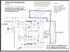
The first pic shows the overall capture. Note it is 0.5s per horizontal division (and offset by 1s). Count out 6 segments for the 3s a 308 case was in the coil.
Now it appears to me, from looking at the scope pic and from watching the LED, that the induction board remains powered for at least period C. I need to probe the Sestos timer itself. It could merely be that it takes a good while for the energy in the induction board to dissipate. You can see it take 770ms for the waveform to collapse.
The vertical voltage division is 50V per division. The voltage across terminals ranges from +112V to -106V. (Note the v sag into and out of the 0.5s mark.) So we have Vpp of 218V => 77 Vrms. This, divided by two, sort of roughly matches the voltage the voltmeter is showing at the input to the induction board.

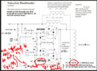
The second pic is a zoom into the more stable part of the capture.

You can see the circuit is resonating at 104kHz.
I have a compact 7 turn coil in 1/8" copper tubing.

A 3 secs
B 0 secs
C 0.5 secs (trap door open)
D 0.5 secs
The first pic shows the overall capture. Note it is 0.5s per horizontal division (and offset by 1s). Count out 6 segments for the 3s a 308 case was in the coil.
Now it appears to me, from looking at the scope pic and from watching the LED, that the induction board remains powered for at least period C. I need to probe the Sestos timer itself. It could merely be that it takes a good while for the energy in the induction board to dissipate. You can see it take 770ms for the waveform to collapse.
The vertical voltage division is 50V per division. The voltage across terminals ranges from +112V to -106V. (Note the v sag into and out of the 0.5s mark.) So we have Vpp of 218V => 77 Vrms. This, divided by two, sort of roughly matches the voltage the voltmeter is showing at the input to the induction board.
The second pic is a zoom into the more stable part of the capture.
You can see the circuit is resonating at 104kHz.
I have a compact 7 turn coil in 1/8" copper tubing.
Last edited:
")
")