• This Forum is for adults 18 years of age or over. By continuing to use this Forum you are confirming that you are 18 or older. No content shall be viewed by any person under 18 in California.

Induction brass annealer redux

I finally crossed the finish line - the annealing assembly is up and running flawlessly. All bugs are dead by now.

The inspiration of this project came from the Shooters Forum (Gina and Eric in particular), Nicola Tesla and Annie Oakley for obvious reasons. Pure chance helped me find the perfect enclosure for this project on the top of a very dirty store shelf. The enclosure had built-in an 8 inch slow speed fan and a transparent side panel, which gave me the idea to install the induction coil inside the enclosure. I also provided a wall plate cable organizer, which shoots the annealed brass outside of the enclosure. [https://www.lowes.com/pd/Eaton-1-Gang-White-Recessed-Cable-Access-Recessed-Wall-Plate/3125961]

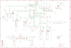
I ordered parts, more or less, from the list Gina had published - actually the contractor, A/V meter, 12 VDC power supply, the push buttons and a 120 VAC fan. Lack of space made me decide that all controls will be handled by a Programmable Logic Controller (SG2-20CR-12D). This gave me ample opportunity to add more functions and to be more precise with timing (annealing and cycle time) . I implemented three modes of operations - Test, Single Timed Shot and Cycling. The Test mode, with a combination of an electronic stop watch, Tempilaq 750 and the moving up and down of the motorized trap gate plate helped enormously to determine the annealing recipe and it saves a lot of brass. On the top of it, I added a "traffic control" - green, yellow and red (annealing) pilot lights to alleviate the otherwise boring process.

I decided to provide cooling from outside the enclosure - similar to the chilling units for a central A/C installed outside of a house. I call this "cooling on the rocks". Instead of crowding the enclosure with a tank with built-in pump, radiator and fans, I'm using an outside pickling jar with a pump and ice cubes.

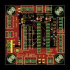
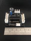
The cooling of the electronics is very effective with both fans mounted in series. I experience no overheating of the capacitors.

My Power Supply is a 750 watts Mean Well 750-48. It refused to be housed in the little enclosure, so I did some remodeling. I liked the current limiting feature, especially when the coil has shorts. On the front I provided 1/4 inch piece of cooper tubing to reach the voltage-adjusting potentiometer.

I can anneal 6 mm Norma BR and 260 Remington, for now. I plan to add some more calibers (my shooting buddies immediately declared that "we" have an annealing machine). They are ready to "cover" my cost at the rate of 2 cents a pop. Since changing the annealing time requires a laptop (the only negative), I'm changing the caliber-specific recipe with adjusting the voltage and the immersion of the cartridge into the coil. I kept my annealing time for the above calibers at 4.83 seconds - 6 mm BR - 44.3 volts/17.5 amps, 260 Rem 54.3 volts/14.8 amps (the Amps are at the end of the annealing). The current is 8 to 9 amps in idle mode.

Also, I experimented with different size coils. I concluded that the magic 1/4 inch under the shoulder dark spot could not be achieved with a very short annealing time (small diameter coils, short annealing timing etc). In my opinion, it appears that some time is required for heat transfer from the neck to the shoulder. So I stuck with Erik's coil.

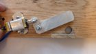
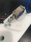
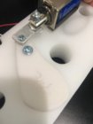
I found that GrocMax's idee-37035.jpg e-37037.jpg e-37038.jpg e-37039.jpg e-37035.jpg e-37037.jpg e-37038.jpg e-37039.jpg a for the trap gate (tennis racket style ) is marvelous: It allows the use of any solenoid regardless of its travel distance. I also admired the craftsmanship of the members of this Forum. Personally, I had only some handyman tools.

Many many years ago, I worked on a similar project for a 150 kilowatts electrical motor-hi frequency generator for quenching iron parts. Now I closed the circle with the new technologies.

I would like to express some thoughts about the annealing machine from New Zealand. Regardless of the cost, the feeding of the brass is very clumsy. All units, presented in this Forum are years ahead in terms of being user-friendly. In addition, the programmed annealing parameters sound to me like a bureaucratic solution - one size fits all - no variance is allowed for different thickness or cartridge alloy or wildcat cartridges.
 
WOW... Oliver, interesting build. I'm curious about your "tennis racket style" trap door, not sure what you mean by that. A picture would be nice. I'm sure future builders would be interested in it, in that my original solenoid is no longer available. External cooling has been used by other builder (connected to a house water line) but a pickeling jar... that is a first. What size jar and with the ice, how many cases can you anneal before the water gets too hot?
Not being a programmer (me, being an old electronic's dinosaur) your PC design is way above my pay grade.
Glad it all worked out for you.. Great build.
Gina
 
Shaped like a tennis racket (paddle), put the pivot point where it needs to be for needed travel and how much the solenoid moves. Travel of solenoid can be multiplied or divided (or 1:1 ratio) depending on where pivot point is located. Used a master chain link between solenoid shaft and end hole of paddle so it doesn't bind.

 
WOW... Oliver, interesting build. I'm curious about your "tennis racket style" trap door, not sure what you mean by that. A picture would be nice...... What size jar and with the ice, how many cases can you anneal before the water gets too hot?
Gina

Attached of one of my prototypes of the solenoid gate.

The "jar" is 1/2 gallon and after 250 case, in may estimable the temperature was about 120 F (the ice was gone).
 

Attachments

  • P1050460.jpg
    P1050460.jpg
    76.7 KB · Views: 236
Hello all, My son and I are starting our build. He is using it for a boy scout project. I am going to try following the plans and drawing FishingDog posted. I have tried to reach out but has not been active for a while. I might have lots of questions as our electronics knowledge is not huge. Also, do any of you all have plans or such for a brass feeder?
 
View attachment 1055276
getting ready to wire it up, using 12v for controller.
Still unsure if i take the Arduino route yet!

I designed a PCB and software to use a PIC to control the start of the timer and manage PWM of the fans. I use an OPB819Z to detect a case in the trap. The PCB is more flexible than my software in that it could totally replace the Sestos timer. I made a completely stupid mistake in my first PCB run and since I had to do a rerun I added room for the additional parts to control the switching of power to the induction board and trap door. Given I already have the Sestos timer I did not redo the software to replace it - if nothing else the Sestos provides a cheap user interface for entering the induction/annealing time. Someone could easily take one of my boards and alter the code to use the I2C connectivity provided to connect to a keypad and display and use the additional switches (Switch 1 and Switch 2) as described above. The board monitors 4 NTC to manage PWM of the fans (2 NTC per fan). The second version of the board should arrive in the next day or two and I will continue with my testing.

EDIT: added pic of old board
 

Attachments

  • Annealer top.png
    Annealer top.png
    21.9 KB · Views: 188
  • Annealer bottom.png
    Annealer bottom.png
    16.2 KB · Views: 187
  • IMG_3222.JPG
    IMG_3222.JPG
    247.7 KB · Views: 150
Last edited:
Another example of a "paddle" trap door. The challenge of getting a short travel (1cm) solenoid to cover/uncover a relatively large hole (e.g. 15mm) is, as Grocmax noted, solved by deploying leverage.
 

Attachments

  • IMG_3219.JPG
    IMG_3219.JPG
    196.9 KB · Views: 353
  • IMG_3220.JPG
    IMG_3220.JPG
    167 KB · Views: 317
Last edited:
Since changing the annealing time requires a laptop (the only negative)

If you are using a USB to serial connector from the laptop to your board you might consider a $8 bluetooth to serial wireless board. You can then interface with your board from a mobile smartphone via one of many free serial comms programs. Saves having to lug a laptop around.

https://www.amazon.com/dp/B071YJG8DR/?tag=accuratescom-20

Only the middle 4 pins need be connected.

For iOS devices you will need an HM10 device like:

https://www.amazon.com/dp/B06WGZB2N4/?tag=accuratescom-20
 
Last edited:
Hello all, My son and I are starting our build. He is using it for a boy scout project. I am going to try following the plans and drawing FishingDog posted. I have tried to reach out but has not been active for a while. I might have lots of questions as our electronics knowledge is not huge. Also, do any of you all have plans or such for a brass feeder?

Hi.... :)

If your knowledge of electronics is not that great, you may just want to build just the basic GinaErick unit. Plans at the beginning of this thread. No programming, no building of circuit boards, pretty strait forward. The only hitch is the trap door solenoid I called out in the parts list is no longer available. Replacement ideas can be found in this thread. Some really great add-on's have been added to the original design, but it gets complicated.
I like a KISS design (Keep It Simple S____D)
So if this is your first build, it is a beginning you can always add more bells and whistles, later on. An Auto Load design can be found on page 51
JMHO... Good luck on your build.

Gina
 
Last edited:
+1 on Gina's post above.

A few other observations. Use 12V wherever possible rather than mains voltage. It's just safer. For example, this 12V automotive relay to switch 48V to the induction board rather than trying to use mains voltage for the switch. Other things can cost a little more but make life a lot simpler and safer - e.g. an IEC AC power inlet which has a fuse drawer built into it. Then you only "need" (it's probably optional) a fuse on the live wire from this to the 12V power supply. This will do the trick. So no open fuse banks etc.

Lastly, I will bet there are a lot of people with excess stuff from their builds. For example, I bought 50 feet of 1/8th copper tubing for $30 to make two coils (I'm building all the DIY parts in duplicate as a friend may 'copy' my build IKEA-style - so two shelfs and trap doors etc). I reckon I have used a quarter of the tubing at most, certainly less than a third. I'd be happy to provide all my excess 1/8 copper tubing for half my cost (i.e. $15 + P&P). Same applies to the 1/4in copper and the various clear tubing (here you buy in lots of 10 feet and use a foot or so). So you might find some economies by purchasing stuff from others. I just need to finish assembly on my side before offering my excess bits and bobs. My enclosure should arrive by the end of this week/early next.
 
I have found a few ideas for the arduino but new to programing so looking forward to the challenge.

BTW I had never done any C programming before and certainly never programmed a PIC. It was a relatively steep learning curve and frustrating at times, but useful because I can use what I learnt in other projects (safety control functions in power amplifiers etc). Personally I think Arduino is overkill for something like this when a little $2 PIC16F1829-I/P can do everything you'll ever need. The Sestos timer's switches can be replaced for a couple of dollars and the requisite programming to control these is 'very easy'. Programming for I2C connected LCD displays and keypads was a bit beyond my current knowledge, however, and since I already had the Sestos I stopped there. I can connect to the board via Bluetooth from my iPhone and so could use that as a UI to enter annealing times etc but I didn't think that was going to be useful for too many others. So I created a board that can be used with the Sestos or with a few optional parts, some programming changes and an I2C breakout module be used to replace the Sestos completely. The only 'issue' is that most of the board is SMD soldering with some rather small parts. But, really, SMD soldering is easier than through-hole. (The board is 5cm/2in square.)

If you want to take a look at the code let me know. The core part for automating the start of the Sestos timer (in single-shot mode) is only about 20 lines and then only because it is monitoring temperatures for an 'overheating' condition and monitoring the IR switch for a case.
 
Last edited:
Mine was about 50 ohms and when tested with 12VDC pulled about 0.25 amps with a regular hall effect multimeter, guess that proves ohms law out. Mine had no label either. Haven't used it yet but plan on changing my current trap door in the near future.


I just measured the so-called 300mA versions I purchased - 15.6 ohms which matches the circa 0.76A current draw I see through my bench PSU. I also measured the "1A" version: 7.8R. I don't think Uxcell have a proper grip on what they're selling.
 
I noticed you didn't use any clamps on the tubing. Advisable?
So far so good. The bigger tubing was a tight fit onto the radiator and the pump so I figured it would be ok. Even when warm it is still snug. Where it connects to the 1/8” tubing I have smaller tube inside the bigger tube so it’s also tight.
Advisable? Probably not
 
BTW I had never done any C programming before and certainly never programmed a PIC. It was a relatively steep learning curve and frustrating at times, but useful because I can use what I learnt in other projects (safety control functions in power amplifiers etc). Personally I think Arduino is overkill for something like this when a little $2 PIC16F1829-I/P can do everything you'll ever need.

It depends on what your comfortable with. An Arduino Nano is less than $5, doesn’t need a separate circuit board and has all the functions you’ll ever need.
 
It depends on what your comfortable with.

Fair

An Arduino Nano is less than $5, doesn’t need a separate circuit board and has all the functions you’ll ever need.

I hadn't seen them that cheap.

But they are logic level voltage only, correct? You still need all the other components to switch 12V, calculate temperature etc etc. Rather than scatter these all over the place it is easy to place them on a board. The Arduino replaces only one of the components in this schematic and a couple of the connectors or maybe I am mistaken.


On another note, what temperature Tempilaq are people using? From the reading I've been doing people seem to use all different temps.
 

Attachments

  • Annealer schematic.png
    Annealer schematic.png
    297.1 KB · Views: 266
Fair


I hadn't seen them that cheap.

But they are logic level voltage only, correct? You still need all the other components to switch 12V, calculate temperature etc etc. Rather than scatter these all over the place it is easy to place them on a board. The Arduino replaces only one of the components in this schematic and a couple of the connectors or maybe I am mistaken.


On another note, what temperature Tempilaq are people using? From the reading I've been doing people seem to use all different temps.

I use 750 degree temp.
 
On an interesting note...on annealing.

Some of my 6br Dasher cases have come to the end of life. (head case cracks) I shoot practice once, maybe twice a week. Do national and local matches 5-6 times a year. It has been 2 years since I bought new brass. (total number of cases I have, is about 600) I anneal my brass right after I come home from the range. resize, de-cap, clean and do all the other stuff. I never had a case failure, never a cracked neck, and my neck tension was always right on. I could not give you an accurate number of firings for my oldest cases, but it has to be up there of 50+

Does annealing help/work.... I think so.

Gina
 
Fair
I hadn't seen them that cheap.

But they are logic level voltage only, correct? You still need all the other components to switch 12V, calculate temperature etc etc. Rather than scatter these all over the place it is easy to place them on a board. The Arduino replaces only one of the components in this schematic and a couple of the connectors or maybe I am mistaken.

No its not logic level only, I drive a solid state relay directly off a digital out. You can run servos directly off the PWM pins as well as fan controls, Temp sensors can connect directly to the analog in. Timers, I2C, Serial etc are built in. You would need a relay if you use a solenoid since they draw a lot of power it seems so I used a servo instead.

I posted this one somewhere in this long thread a while back. I used a servo and photo resistor driver since I had them but your could connect directly with a little more code. They are less than $5 each. If you haven't written any "C" it can be more than a little daunting but the physical setup is easy.

This is just an FYI, As Gina said, build it however you want !
 

Attachments

  • annealer.jpg
    annealer.jpg
    50.1 KB · Views: 314

Upgrades & Donations

This Forum's expenses are primarily paid by member contributions. You can upgrade your Forum membership in seconds. Gold and Silver members get unlimited FREE classifieds for one year. Gold members can upload custom avatars.


Click Upgrade Membership Button ABOVE to get Gold or Silver Status.

You can also donate any amount, large or small, with the button below. Include your Forum Name in the PayPal Notes field.


To DONATE by CHECK, or make a recurring donation, CLICK HERE to learn how.

Forum statistics

Threads
164,753
Messages
2,183,585
Members
78,500
Latest member
robbsintexas
Back
Top