• This Forum is for adults 18 years of age or over. By continuing to use this Forum you are confirming that you are 18 or older. No content shall be viewed by any person under 18 in California.

Induction brass annealer redux

With the 101 pure copper tube I used (because it is slightly more 'efficient') I couldn't find thinwall at a decent price, so bend radius pinch can be an issue. With thinwall 12x tube it really isn't necessary to use a filler. Half hard tube will bend without collapsing easier than fully annealed tube, just use a cheap bending tool available at your local hobby shop or on the net-

https://www.towerhobbies.com/cgi-bi...MIr5Sar6rV4QIVzZyzCh0DYA5xEAQYAiABEgJmTfD_BwE

You can make some pretty tight radius bends with this, it do take some practice though.

Square or D profile tube is supposed to even more efficient, I've wanted to make a press die for turning round to square for quite awhile now. It ain't difficult, but you'd need to fill it during the bending process, because that WILL kink or collapse.

Not sure what the "12x tube" is, I just got a piece about 3 feet long that I am not sure if it's soft or hard this is why I want to use filler just because it's so simple to do it, why take chances, fill it with water or fine sand I got, seal the ends and band away. I got a lathe so I can machine any mandrel I want, I can even make the round "thread" in delrin rod for tube to follow exact spacing but it's probably not necessary. Forming coil should be simple too, chuck the mandrel, lock the spindle, rotate, bend, repeat. Regarding bending tool, I don't really see the need for it. I've read the link you sent on coil design I've read it and saved it in my favorites but even though it was pretty good information overall it did little to help in our quest for better coil, the breakthrough I saw was Fluxeon ferrite with litz wire coil as well as interesting variation they did for Giraud, it looks like ferrite oring that had opening cut out and simply wire wrapped. Once I build the normal coil I will play around with that. https://fluxeon.com/product/annie-flux-concentrator-coil/

Regarding the square or D profile tubing, I have small milling machine and small hydraulic press and you stirred my brain, I should be able to make this fairly easy. My guess that D shape would bend more naturally than square tube I could probably even make it out of aluminum, square die would be easier to make. You can share your idea how you envision the forming die.
 
Dima-

Sorry, fat fingered and I keep forgetting this is a very international forum, and us Yanks should explain those silly imperial units and US terms. 1xx series copper is the description of the alloy, they ain't all pure. 101 copper is the purest, its the most electrically conductive.

101
102
110
122
145
182

All these are called pure copper by some but they ain't. Only 101 and 102 are considered pure.
I believe 110 is copper recovered from scrap with most of the alloy elements removed, but not all. I'd guess this is what most people are getting when they get a generic 'pure copper'.

122 has phosphorus and is weldable.

145 and 183 are alloyed for mechanical properties like strength or machinability.

Fill with water and freeze, molten salt and let harden, cerrosafe, or cap, seal and pressurize or with water/liquid fill are just a few of the techniques used to keep wrinkles and collapsing to a minimum when bending. Lead or tin would work. Lots of different ways to support the tube internally while bending.

And yes, just make a simple two piece form die, use an arbor press, and profile a short distance at a time till the length of tube needed to complete the coil winding portion is done. D or square shape would be quite easy to make a die set for. Then comes the tough part- bending the D or square tube. This would probably produce many failures before I ever got the process correct and to make a good one.

EDIT- You were maybe thinking how to keep the tube straight and flat and not twisted as it comes thru the die? On the exit end of the die the tube has to pass thru a close fitting hole in a plate, or the die itself that keeps it from twisting. That's about as far as I got with it was thinking the process thru, I have no idea how its actually done in the industrial world. Us hobbyists need to KISS- Keep It Simple, Stupid.
 
Last edited:
I made the coil last night. Closed one end and realized I can't fill with water it won't go in :) So I cut it off and used the pump to run water through it and sealed both ends than I drilled a hole in a wood dowel to keep the tube straight, I also took PVC and set my gears for 5 tpi thread pitch (~5.1mm) since I figured the tube is .187" OD, so if I put a loop every .2" that should leave some room but I think the copper tube widened a bit because there was no space between, I had to stretch it in the end, next time I'll use 4 TPI - 1/4" wide loops. What really surprised me is I measured my copper piece to be 41" long (104cm) and I wasted maybe couple inches but it was barely enough to make the loop, I thought I would have longer leads left. Regarding square tube die, my 1st though was like you mentioned 2 part and press but than I thought I can machine 2 rollers, either half a square on each side or even better V shape (diamond) and just run the tube through it with little crank handle attached maybe even a reducing gear. This way I can actually make multiple passes and should go much quicker.
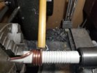
 

Attachments

  • 2019-04-18 (2).jpg
    2019-04-18 (2).jpg
    510.7 KB · Views: 277
  • 2019-04-18 (1).jpg
    2019-04-18 (1).jpg
    380.6 KB · Views: 285
  • 2019-04-18.jpg
    2019-04-18.jpg
    290.7 KB · Views: 263
Last edited:
Found couple interesting things. 1st a putty by AlphaForm that concentrates flux, it seems like exactly what we need, a concentration in the neck/shoulder and same time can keep the case from tilting. I sent them a message for price quote. https://www.google.com/imgres?imgurl=https://fluxtrol.com/inc/images/fluxtrol-gallery/Alpha_Form_Moldable_Magnetic_Flux_Concentrator.jpg&imgrefurl=https://fluxtrol.com/induction-heating-technical-gallery&docid=5Roz0k3WzzZVKM&tbnid=Q7CpsUeYd63bNM:&vet=10ahUKEwja0_u39tfhAhUosVQKHSmBBr0QMwhQKBAwEA..i&w=720&h=540&bih=722&biw=1536&q=Flux Concentrator Coil&ved=0ahUKEwja0_u39tfhAhUosVQKHSmBBr0QMwhQKBAwEA&iact=mrc&uact=8
Another thing I was looking at Annie Flux Concentrator Coil and it's $57 before shipping. It looks like a square Ferrite transformer core that I found on Amazon 5 for $20 but where and which Litz wire, I found a chart online that says 32AWG wire to be used for 100Khz https://www.amazon.com/dp/B0146OG8VK/?tag=accuratescom-20
 
Last edited:
KISS.. A yup. :D
Gina, Thank you and Eric for all your work on this project. I have built yet another version of this annealer standing on your shoulders. Now that it is functional I have a question for you on interpreting the results. I annealed a 20 vartarg case using both 750 and 400 degree tempilaq. I will upload the picture. The question arises from the fact that the Tempilaq changes color as it should and based on that I think the case annealed correctly. The troubling issue is that the case does not change color at all like it did with other annealing methods. I did not get the normal dis-colorization to just below the shoulder. The other side of the case looks like clean brass. I am not sure if I should just trust the tempilaq or pursue this further. Any insight you might have would be helpful. Regards.. Kurt
 

Attachments

  • IMG_3083.jpg
    IMG_3083.jpg
    428.8 KB · Views: 168
Last edited:
Gina, Thank you and Eric for all your work on this project. I have built yet another version of this annealer standing on your shoulders. Now that it is functional I have a question for you on interpreting the results. I annealed a 20 vartarg case using both 750 and 400 degree tempilaq. I will upload the picture. The question arises from the fact that the Tempilaq changes color as it should and based on that I think the case annealed correctly. The troubling issue is that the case does not change color at all like it did with other annealing methods. I did not get the normal dis-colorization to just below the shoulder. The other side of the case looks like clean brass. I am not sure if I should just trust the tempilaq or pursue this further. Any insight you might have would be helpful. Regards.. Kurt

How many times have you annealed those cases ? Just observation on my part, but some cases stop changing color after a few anneals.Trust the tempilaq. I've annealed and used some cases more than 20 times, with out any problems. I've also noticed no color or very little color change in the annealed area.
hopes this helps.
Yes that helps. I think that when I used to torch anneal the flame burned the outside a little and that was the largest culprit for the color change. The opposite side of the case shows no color transition. Does the tempilaq look about right to you on that case?
My system runs at 102.4KHz which gives a skin depth sightly deeper than the neck wall thickness so that should be fine. It is a small case and the power supply current ends up around 11 amps by the end of the anneal. My idle current is about 8.7 amps which is a little higher than yours but in the ball park. I am a retired electrical engineer who was looking for a better way to anneal and when I searched on induction I found your project. When I get the thing looking a little better I will post it. i have read all of your and Eric's posts (everybody else as well) and have tried to follow the best practices as they developed.
Best regards, Kurt
 
Last edited:
I have been using the 750 degree tempilaq in a completely dark room and can get a change of colour on the tempil but no change on the case. I found when the case went slightly glowing then the case changed colour.

I am no sure exactly what to make of this but will err on the shorter heating time. I dont think it really takes much to make a change to the brass.
Thank you for the reply. I suspect the case changing color is due to over heating and oxidation on the outside.
 
I'd be wary of having the tempilaq change colour so far down the case wall. I trashed a stack of cases doing similar. The neck - shoulder junction became too soft and was knocked out of alignment resizing. As for brass colour change, I'd ignore that. You'll get a difference merely based on how clean the brass is.
 
I'd be wary of having the tempilaq change colour so far down the case wall. I trashed a stack of cases doing similar. The neck - shoulder junction became too soft and was knocked out of alignment resizing. As for brass colour change, I'd ignore that. You'll get a difference merely based on how clean the brass is.
Thank you I will lower the case a tenth of an inch and test it again.
 
So I have had some time at home, for the past few days. I have had most of the parts for the original build (V2), that was kindly posted by Gina. I'm still waiting on the volt current meter / shunt, and I've substituted 12V fans for the PCB and radiator. I also added an extra led, as a power "on / off" indicator. Anyway, I jumped on in, and started in on building it! So apart from the parts I'm waiting on, I only need to finish the case (sides, back and top), and to position the radiator, and pump, then connect the coolant tubing. All of the wiring is done, except for what goes to and from the shunt and volt / current meter.
So of course I wanted to make sure what I have done, works. Plugged it in, turned it on, both power supplies seem to be working (leds going on both), fans, coolant pump, on/off led, timer display all "working". I took a crack at setting the timer, seemed to get the timers sorted. Then disappointment, I tried to get the timer to cycle through A, B, C, and D. And nothing happened....so hopefully it is just that the shunt / volt / amp meter needs to be connected. I thought that I the timer would go through the sequence, and the PCB wouldn't work. But that pause for placing a new case to be annealed, the time for the PCB to be energised, and the "trap door" would operate.
EDIT: traced why the timer functions wouldn't work, faulty start switch. Amazing what you can figure out, after sleeping on it :). Boy, that contactor is loud! I know that in one of the posts, there was mention of a satisfying "clack" or similar, I thought something had broke! So I'm just a little chuffed that it all seems to be working. Just need the final parts to arrive. :cool::D
If anyone has run into anything similar, or has help / suggestions, I'd appreciate it.
cheers
Brendon
 
Last edited:
2019-04-26 (1).jpg 2019-04-26 (2).jpg 2019-04-26.jpg Got my 1800 watt board from Banggood and the board arrive banged pretty good :) heatsinks with mosfets bend in and broken wire studs that hold them to the board. I am still waiting for my 2400 watt power supply ($65+$5 shipping) but went ahead and tested with my 500 watt supply. I found the idle current pull was pretty high, I am not sure if this board doesn't like my 1" coil or if 3/16" tubing in the coil is too much but I am pulling 8.5A at 30 Volts, my power supply has full range of voltage adjustment. The most alarming thing the front 2 capacitors are heating up PCB under it to extreme temps, On the left side of the board under 1st capacitor I was getting about 72F degrees after few minutes of work whereas on the right it exceeded 300F! Even on idle it climbed over 220F. The anneal did work though, at 30V it took about 5 seconds and at 35V it took 4 seconds to anneal 223 brass. That's only 350-400 watt of power, I can imagine with flux concentrator I could drop the power requirements even lower. I am going to try to return/exchange the board. The Banggood are not easy folk to deal with. P.S. The brass connector that you see didn't come with the board, I machined them, original design was for coil to be on top of the board but I was concerned about water leak.
 
Hi Dima Prok the idle current seems about right I would go chasing problems based on that. The temperature increase near the capacitors is that close to the posts? I found a similar thing and put it down to poor post connection to board and the heating in the traces themselves from what I could tell. I did a couple of mods to try and lessen this. They had a medium effect but not a total fix. Also the heat sinks under the board.
 
Really? At 35V I was pushing 10 amps on idle! I feel like something is not right where one side of the board is cool and the spot under 2 capacitors next to posts/coil are getting such crazy heat output. I am wondering if I am maybe the tube ends are too close to the board and introducing eddy currents, I'll try to use original posts and put coil back on top to see if that makes a difference. I bought special non conductive glue to attach heatsinks to the bottom of PCB but before I glue them I want to make sure I don't have defective board. P.S. My post connection is nice and tight.

Found this warning not to use automotive fuse but a high speed magnetic circuit breaker http://www.neon-john.com/Induction/Roy/Roy.htm
 
some pics of my annealer, thanks to this post....054.jpg 053.jpg 055.jpg
The top and both side are held on with clips, and can be easily removed, for access or extra cooling (still waiting on amp/ voltmeter, before a run the induction board). Might still add another cooling fan.
I had trouble getting the solder joints on the copper tubing to seal, so I used a two part product,"Knead It", and no more leaks. Added a observation window to the top....maybe I need some more leds on the inside of the annealer?
Big thanks again to Hollywood and Gina

cheers
Brendon
 
Looking good. Check the wiring on the amp/volt meter when you get it. The one I got didn’t work when it was wired as per this post and eventually pixie dust rose from the back of it complete with that wonderful smell you get when you know things have just gone FUBAR. If in doubt ask here as I think GrocMax had the correct wiring for these “other” units that look the same. My 3rd unit was the same as Gina’s one so it worked fine when wired as per post 1 or 2. Just a heads up.
 
Last edited:
Looking good. Check the wiring on the amp/volt meter when you get it. The one I got didn’t work when it was wired as per this post and eventually pixie dust rose from the back of it complete with that wonderful smell you get when you know things have just gone FUBAR. If in doubt ask here as I think GrocMax had the correct wiring for these “other” units that look the same. My 3rd unit was the same as Gina’s one so it worked fine when wired as per post 1 or 2. Just a heads up.
cheers for the heads up.:)
 
Ok Guru's....please clear up for me some questions on the Volt/ Amp meter.
1. It is the red and black wires, on the 2 wire plug that go to the 12V power?
2. It is the wires from the 3 wire plug that go to the shunt, and the positive side of the contactor?
3. How do I tell which volt/ amp meter I have, as per McHaggis's post? In which case the wiring would be different.

cheers
Brendon
 

Upgrades & Donations

This Forum's expenses are primarily paid by member contributions. You can upgrade your Forum membership in seconds. Gold and Silver members get unlimited FREE classifieds for one year. Gold members can upload custom avatars.


Click Upgrade Membership Button ABOVE to get Gold or Silver Status.

You can also donate any amount, large or small, with the button below. Include your Forum Name in the PayPal Notes field.


To DONATE by CHECK, or make a recurring donation, CLICK HERE to learn how.

Forum statistics

Threads
165,338
Messages
2,193,685
Members
78,845
Latest member
baglorious
Back
Top