
Install the app
How to install the app on iOS
Follow along with the video below to see how to install our site as a web app on your home screen.
Note: This feature may not be available in some browsers.
You are using an out of date browser. It may not display this or other websites correctly.
You should upgrade or use an alternative browser.
You should upgrade or use an alternative browser.
Induction brass annealer redux
- Thread starter Gina1
- Start date


Aliexpress is another option, for the parts as well, including the board.Hi All,
I'm reading through this thread and am up to page 30.
I can't see an available SainSmart induction heater on eBay or Amazon. I did some searches on this thread trying not to be lazy, but nothing jumped out discussing reliable alternatives. Am I missing something? Has this been discussed? Is there another option?
Thanks.
I managed to get some smoke to come out of the on/off switch which sits between the power supply and the relay. This switch is a essential item if anything goes wrong so you can immediately turn off the power. It was a rocker switch and I have now replaced it with a toggle switch. The old switch was 10 amps @ 125VAC and 6 amps @ 250VAC, the new toggle switch is 20A @ 255V. I was not able to locate any DC switch over 12V, so no way was that going to handle 48V.
I have noticed for the last few months that the time taken to anneal has been slowly increasing, from 6.8 to 8.6 seconds for my 6.5 Creedmoor. I have checked and rechecked very single item and re-soldered every joint to no avail. Looks like it was this rocker switch all the time.
The power readings of the annealer with the new toggle switch have now increased significantly 10.5A to 15.5A and 420W to 550W. This of course has also reduced the annealing times of all cases - confirmed with Tempilaq 750. The new switch is the only change made so the old switch was inhibiting the current flow.
I managed to get some smoke to come out of the on/off switch which sits between the power supply and the relay. This switch is a essential item if anything goes wrong so you can immediately turn off the power. It was a rocker switch and I have now replaced it with a toggle switch. The old switch was 10 amps @ 125VAC and 6 amps @ 250VAC, the new toggle switch is 20A @ 255V. I was not able to locate any DC switch over 12V, so no way was that going to handle 48V.
I have noticed for the last few months that the time taken to anneal has been slowly increasing, from 6.8 to 8.6 seconds for my 6.5 Creedmoor. I have checked and rechecked very single item and re-soldered every joint to no avail. Looks like it was this rocker switch all the time.
The power readings of the annealer with the new toggle switch have now increased significantly 10.5A to 15.5A and 420W to 550W. This of course has also reduced the annealing times of all cases - confirmed with Tempilaq 750. The new switch is the only change made so the old switch was inhibiting the current flow.
Scratching my head as to why you would want a switch between the 48 volt PS and the induction relay ?? That is the relays job and can be un-energized by hitting the "stop" button.
But this is every bodies build and how you build it is up to you.
Since your problem of increasing annealing time has been occurring over time, I would think induction PCB is going bad,and would even hazard a guess that one or more of the capacitors are degrading.
JMHO
Gina
Gina, the other reason would be the degradation of the contacts between the coil and the board. The increased resistance - even in a very small degree - would be very critical given the fact that practically the applied voltage is ~0.
?? Please explain??Gina, the other reason would be the degradation of the contacts between the coil and the board. The increased resistance - even in a very small degree - would be very critical given the fact that practically the applied voltage is ~0.
I have auto feed on my machine, and the annealer is initialized by a case dropping past a 12V induction proximity sensor which starts the timer. That timer triggers the relay to energize the annealer. Pretty much the same basic design as everyone else. This switch is the only stop button that I have.Scratching my head as to why you would want a switch between the 48 volt PS and the induction relay ?? That is the relays job and can be un-energized by hitting the "stop" button.
But this is every bodies build and how you build it is up to you.
Since your problem of increasing annealing time has been occurring over time, I would think induction PCB is going bad,and would even hazard a guess that one or more of the capacitors are degrading.
JMHO
Gina
Before I installed the first switch a case rested up against the coil and shorted it out. Turning off at the wall had no immediate effect as power supply takes about 6 seconds to fully discharge its power if switched off. But by having this switch I can cut the power to the annealer immediately. That case shorting out cost me a new power supply and some refinements to the dropping process. Turn this switch off at any time for any reason and the 48V feed to the relay is cut immediately thereby stopping any power flowing to the annealer.
I think my PCB is fine. I thought that was the problem too when the annealing times started to increase so I bought a second PCB and swapped them over, with no change in power readings. Quite disappointing. The initial 'normal' power levels have now returned since this new switch was installed, so my reasoning is that the previous switch was slowly burning out and thereby reducing the power throughput. Anyway, it is 100% again now, and all fixed with a $4.50 toggle switch.
As you say, this is my personalized build of your initial design and, other than the auto feed, it is probably quite unique in the way I have approached it. We are all solving our problems in isolation and therefore each solution will be unique at least to some degree. I have put nearly 5,000 cases through mine now so this little hiccup with the switch is nothing to be concerned about. Hopefully many thousands more to go.
I have auto feed on my machine, and the annealer is initialized by a case dropping past a 12V induction proximity sensor which starts the timer. That timer triggers the relay to energize the annealer. Pretty much the same basic design as everyone else. This switch is the only stop button that I have.
Before I installed the first switch a case rested up against the coil and shorted it out. Turning off at the wall had no immediate effect as power supply takes about 6 seconds to fully discharge its power if switched off. But by having this switch I can cut the power to the annealer immediately. That case shorting out cost me a new power supply and some refinements to the dropping process. Turn this switch off at any time for any reason and the 48V feed to the relay is cut immediately thereby stopping any power flowing to the annealer.
I think my PCB is fine. I thought that was the problem too when the annealing times started to increase so I bought a second PCB and swapped them over, with no change in power readings. Quite disappointing. The initial 'normal' power levels have now returned since this new switch was installed, so my reasoning is that the previous switch was slowly burning out and thereby reducing the power throughput. Anyway, it is 100% again now, and all fixed with a $4.50 toggle switch.
As you say, this is my personalized build of your initial design and, other than the auto feed, it is probably quite unique in the way I have approached it. We are all solving our problems in isolation and therefore each solution will be unique at least to some degree. I have put nearly 5,000 cases through mine now so this little hiccup with the switch is nothing to be concerned about. Hopefully many thousands more to go.
OK, Now I understand your logic behind installing the switch. Would not having a "stop' switch wired into the timer (terminals 1-12) de-energize the power relay, immediately removing the 48 volts from the PCB, do the same thing? I think you posted some pictures of your build a ways back, as I remember it is a "nice machine" !! As you say we each come up with our own solutions.
Just to note... My machine is coming up on 3 years operation. Thousands of cases later it is still working as well as when it was first built.
I have used a different timer, so probably wouldn't work for me. I needed one for my auto feed that could be initiated by the proximity switch and the instructions for the one you guys all use were not completely clear that it would accept that input signal. This one certainly does and work well.

I have used a different timer, so probably wouldn't work for me. I needed one for my auto feed that could be initiated by the proximity switch and the instructions for the one you guys all use were not completely clear that it would accept that input signal. This one certainly does and work well.
View attachment 1104897
"Ahhhhhh So" say the wise man.
")
I did an entire price and availability of the components listed to build the annealer as per items listed on page 1 of this post. There are a couple questions that have arose from my research today. I hope someone can lend me some assistance with...
ITEM #1 SainSmart1000W ZVS low voltage induction heating board I'm having a hard time locating this exact board. Is their an alternate board that functions well in its place? Also, I see some induction board already come with a coil. That would save me time if I could just use the one that came with the board is there a board plus coil combo that works fine?
ITEM #2 34462 Varistor 130VAC Part number no longer recognized by JAMECO . Does anyone have good Part Number?
ITEM #3 2202335 Solenoid Tubular-pull 12VDC Part number no longer recognized by JAMECO . Does anyone have good Part Number?
That's about it, I will order everything all at one time. Once I locate all components to build this project. I appreciate any advice or suggestion that could further assist me with the build. I can't Thank you all enough for the amount of effort that has been involved into this project.
I have auto feed on my machine, and the annealer is initialized by a case dropping past a 12V induction proximity sensor which starts the timer. That timer triggers the relay to energize the annealer. Pretty much the same basic design as everyone else. This switch is the only stop button that I have.
Before I installed the first switch a case rested up against the coil and shorted it out. Turning off at the wall had no immediate effect as power supply takes about 6 seconds to fully discharge its power if switched off. But by having this switch I can cut the power to the annealer immediately. That case shorting out cost me a new power supply and some refinements to the dropping process. Turn this switch off at any time for any reason and the 48V feed to the relay is cut immediately thereby stopping any power flowing to the annealer.
I think my PCB is fine. I thought that was the problem too when the annealing times started to increase so I bought a second PCB and swapped them over, with no change in power readings. Quite disappointing. The initial 'normal' power levels have now returned since this new switch was installed, so my reasoning is that the previous switch was slowly burning out and thereby reducing the power throughput. Anyway, it is 100% again now, and all fixed with a $4.50 toggle switch.
As you say, this is my personalized build of your initial design and, other than the auto feed, it is probably quite unique in the way I have approached it. We are all solving our problems in isolation and therefore each solution will be unique at least to some degree. I have put nearly 5,000 cases through mine now so this little hiccup with the switch is nothing to be concerned about. Hopefully many thousands more to go.
I still don't understand why you can't wire the Stop switch in the wiring between timer and relay. If relay doesn't get voltage , annealer no worky. ;-) But new larger switch in main DC power line and it's back again....Does the switch get warm? ... HB
Read back a few pages there are links to the ZVS board on Ebay as well as the Solenoid and many more parts. The Varistor is only needed if you go with 110V mains voltage. I would say the majority of builders have used 12V DC for this and other components and use Diodes to protect the components.
In my annealer with the auto feed the timer is initiated by an proximity switch as a case drops past it. This uses 12V to energizes the relay and activate the circuit for 48V to the annealer. If the relay seizes/fuses/sticks in the closed position, as has happened to me, and the stop switch is after the relay the power will continue to flow to the relay unless the power supply is turned off at the wall, and that takes time to discharge. This would very quickly lead to overheating the relay and permanent damage. By having the switch before the relay the power can be stopped instantly and before any damage can be done to the relay. By putting the switch after the relay it does protect the annealer but not the relay. No the switch doesn't get warm. Works for me.I still don't understand why you can't wire the Stop switch in the wiring between timer and relay. If relay doesn't get voltage , annealer no worky. ;-) But new larger switch in main DC power line and it's back again....Does the switch get warm? ... HB
If the relay seizes/fuses/sticks in the closed position,as has happened to me Ok I got it now. I've had the relays seize in the beginning too when I used the smaller ones. It's a scramble to get the plug or AC unplugged from the wall or turned off and as you say the voltage has to bleed down. More time to fry brass or damage something. Then I went to the larger relays and now no problem. Got it now, Thanks....HBIn my annealer with the auto feed the timer is initiated by an proximity switch as a case drops past it. This uses 12V to energizes the relay and activate the circuit for 48V to the annealer. If the relay seizes/fuses/sticks in the closed position, as has happened to me, and the stop switch is after the relay the power will continue to flow to the relay unless the power supply is turned off at the wall, and that takes time to discharge. This would very quickly lead to overheating the relay and permanent damage. By having the switch before the relay the power can be stopped instantly and before any damage can be done to the relay. By putting the switch after the relay it does protect the annealer but not the relay. No the s witch doesn't get warm. Works for me.
Attachments
Thanks David,
I ordered the correct board today. Is their a updated schematic with the parts list showing the revised build using 12 VDC relay instead of a 120 VAC. Why have the majority switch over from the original drawing? I don't need an auto feed just want to anneal. Automation is more trouble than it's worth in my opinion, plus I enjoy the process of handholding.
I ordered the correct board today. Is their a updated schematic with the parts list showing the revised build using 12 VDC relay instead of a 120 VAC. Why have the majority switch over from the original drawing? I don't need an auto feed just want to anneal. Automation is more trouble than it's worth in my opinion, plus I enjoy the process of handholding.
Hello Mike....
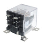
Gina1 here. To answer your question, I used the 120 VAC coil relay, because that was the one I had at the time. Also I used that one because it being a relay, it is also called a contactor.
High current capabilities and a large distance between contacts. Which reduces arcing. A problem that has pop'ed up when some builders have used smaller relays (ie 12V auto relays)
Similar threads
- Replies
- 74
- Views
- 47,361
- Replies
- 0
- Views
- 1,576
Upgrades & Donations
This Forum's expenses are primarily paid by member contributions. You can upgrade your Forum membership in seconds. Gold and Silver members get unlimited FREE classifieds for one year. Gold members can upload custom avatars.

Click Upgrade Membership Button ABOVE to get Gold or Silver Status.
You can also donate any amount, large or small, with the button below. Include your Forum Name in the PayPal Notes field.
To DONATE by CHECK, or make a recurring donation, CLICK HERE to learn how.
Click Upgrade Membership Button ABOVE to get Gold or Silver Status.
You can also donate any amount, large or small, with the button below. Include your Forum Name in the PayPal Notes field.
To DONATE by CHECK, or make a recurring donation, CLICK HERE to learn how.