Follow along with the video below to see how to install our site as a web app on your home screen.
Note: This feature may not be available in some browsers.
This Forum is for adults 18 years of age or over. By continuing to use this Forum you are confirming that you are 18 or older. No content shall be viewed by any person under 18 in California.
I provided a link to the spec sheet for the supply including its protection mechanisms. You tested the voltage condition and I very much doubt there's a temperature fault. So it's clearly not behaving correctly. Hopefully Jameco will exchange it.
Yes but note in your image
V+ comes from the PSU driving the load (the annealer). Just make sure the volt/ammeter can handle a 48V supply. (In all other respects it is wired as other meters of this type. The return from the load is passed across the shunt. The ammeter measures the voltage drop across the shunt (thin wires shunt to com and Ain) and from that deduces the current given the resistance of the shunt is known.) V+ still needs to come from somewhere. The diagram on the right has it coming from the load PSU. The boxes on the left - which aren't checked - reference either an 8-18V V+ range or a 3.5-30V V+ range. Note also the message "please use isolated power to supply the meter". I don't think this is the source of your PSU issue but check the ammeter specs to ensure it can handle 48V as it's power source V+ (quite separately it may measure a wider range than its applicable supply range).
I believe that sticker is a one size fits all type, nothing else makes sense. When I look at how other people wired theirs (via reviews), mine was also wired correctly. There are two adjustment screws on the board for calibration however the indicated values correspond with my multimeter.
From Drok
“Three terminals DROK volts amp tester is equipped with three terminals. The power supply is taken from the test loop. No additional power supply is required.”
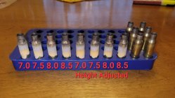
I’m using 308 cases for testing, regular brass cases I guess. I tried Barnes, PMC, and Starline.
Coil isn’t shorted. Before I made the video I stretched the coil to make sure it wasn’t touching anywhere, that’s why the goofy shrink wrap zip tie is on there holding it back together. When it was stretched I was still having the same issue.
The ZVS is only labeled + and -, I’m afraid to switch polarity. What will happen if I switch the connection and it’s hooked up backward? I sent the first one back however I have another coming so I’ll be testing that too.
I ran the unit with the ammeter totally disconnected and the PSU cut out at the same interval.
I will have to play around with testing various other loads on the PSU. I‘ll post the result.
It's not that the wiring needs to change, it's that the part needs to be able to handle a 48V supply. When I Google that part number a multitude of different ones come up but all seem to have a supply range of 3.5-30V. I would check and make sure.
For example, at this link there's almost every permutation of this device
Interesting, I’ll check. Even if I power it from a separate supply, I’ll still need to connect the PSU lead to the center terminal to measure volts/amps, and that will be 42-48 volts, it’s rated 4.5-100 volts. If I wire my 12 volt power supply to the solder points on the board I suppose it’ll keep the screen from blanking out when the PSU trips!
Note the first question in Q&A and answers thereto. Max 30 VDC power source.
However looking at the DROC website (where the images look more like yours) they state it is powered from the PSU under test and separately state a measurement range up to 100V. They don't list a power supply limitation. In other words it's a bit ambiguous which is typical for these cheap type parts.Their website links to this Amazon part:
Buy DROK 0.39 Inch Current Voltage Tester, DC 4.5-100V Digital Multimeter, 0-50A Volt amperage Meter, Red Green Dual LED Display, Volt Amp Meter Gauge Panel for Car Automotive: Voltage Testers - Amazon.com ✓ FREE DELIVERY possible on eligible purchases
Using SGK's diagram (post 2979) as a guide, can you draw out how your units major components are connected (main power, power supplies, ammeter and shunt, relays, switches, ZVS board...skip little stuff like pumps and fans and lights so it is simpler to view)?
I saw the still pics at the end of your video, but its impossible to decipher from that.
It just occurred to me that I don’t utilize emoji’s and such, if my replies seem short please interpret them as they are, grateful and appreciated, thanks everyone!
It probably is already, but I think the wiring for timer module relay to activate the larger ZVS relay should look more like the large red box in my edited image, rather that the small red box...
Other than that, if the ammeter/shunt are correct (can't say as they are different than the one I used with a built in shunt) I don't see any obvious problems...
View attachment 1335928
It probably is already, but I think the wiring for timer module relay to activate the larger ZVS relay should look more like the large red box in my edited image, rather that the small red box...
Other than that, if the ammeter/shunt are correct (can't say as they are different than the one I used with a built in shunt) I don't see any obvious problems...
There are two ways to wire my timer, like you pictured and wired separately, I have tried both. When I had the SSR relay it was necessary to separate the power source from the switch for some reason.
The relay is working with an audible, “click” on and off. Good catch, thanks!
Sounds like what's happening is when you put a case in the coil the current exceeds what the power supply thinks it's safe and shuts down. So your power supplies is acting like the first case protection mode.
I agree. And think the power supply is OK. I would recommend to taooffunk to deep just the neck and shoulder of a case (upside down with gloves) to see how the current develops. If the power supply does not shut down, build another coil with the dimensions of original Eric coil.
But the power supply is NEVER meant to shut down on on an over-current situation. It is meant to merely LIMIT itself at 105-125% of rated power which is 15.7A. It is only meant to shut down in the case of an Over Temperature and Over Voltage condition. His supply is shutting down and way before reaching anything close to 15.7A. He tested for an Over Voltage condition and it wasn't happening. So either it's completely faulty or hitting an Over Temp condition (in which case something is wrong anyway).
I agree. And think the power supply is OK. I would recommend to taooffunk to deep just the neck and shoulder of a case (upside down with gloves) to see how the current develops. If the power supply does not shut down, build another coil with the dimensions of original Eric coil.
Well, it may have been the ZVS board. I just installed the new board and have had no instance of the power supply cutting out. I was able to get cases red hot, albeit after 10 seconds. I have the PSU voltage turned up to 45 volts and am peaking out at 10.5 amps. More to come...
I am required at the grill for dinner. If all goes well I'll be posting later with more good news. Thanks again to everyone contributing to this discussion. My spirit is lifted!
That's good news, but you have some more coil and voltage tuning to do to shorten the time. The closer the ID of the coil is to the case OD the better the coupling will be that should lead to faster heating with the same amount of power.
I'm in the infancy of adjusting the time and depth of the case in the coil. I'm going to do more testing and post my build when I have a coherent description. So far it looks promising since the new induction board has been installed. I have a slightly smaller diameter coil to try which may bring my run times down. I'm maxing out at 11.5 amps however 8 seconds is a bit longer than I'd like.
Once again, thanks for brain storming with me and helping get this unit operating!
The 700 degree Tempilaq isn't adequate however it's all I have.
P.S. I was not anticipating the board was the problem, I was surprised when it turned out to be the culprit.
This Forum's expenses are primarily paid by member contributions. You can upgrade your Forum membership in seconds. Gold and Silver members get unlimited FREE classifieds for one year. Gold members can upload custom avatars.
This site uses cookies to help personalise content, tailor your experience and to keep you logged in if you register.
By continuing to use this site, you are consenting to our use of cookies.


")