Follow along with the video below to see how to install our site as a web app on your home screen.
Note: This feature may not be available in some browsers.
This Forum is for adults 18 years of age or over. By continuing to use this Forum you are confirming that you are 18 or older. No content shall be viewed by any person under 18 in California.
I returned it. That board was strange. The soldering was clean and nice, the components all looked good, there were no scorch or burn marks. Whatever was wrong with it wasn't apparent to me. It looked like a gem compared to the first board I had.
I 'THINK' I read somewhere in this forum that the presence of the brass case won't affect the frequency. I made a coil for 50 BMG that oscillated at 92KHz without brass and 110KHz with. I also read that lower frequencies are for thicker materials and higher for thinner. The BMG brass is thicker so I was shooting for around 90KHz (not knowing if that much would really make a difference) but was surprised it went up so much with the brass.
YMMV
I replaced my failed 36V 1000w power supply with a Meanwell RSP 1000-48v and it seems to work but takes 2 sec longer to anneal. The voltage drops to around 30v and 700w when annealing. Is this because it’s 48v instead of 36v or is the power supply limiting it?
Sounds like the supply was trying to supply more than 20A at 48v so it folded back.
It appears the case in the lower right was heated a bit too far down.
Sounds like the supply was trying to supply more than 20A at 48v so it folded back.
It appears the case in the lower right was heated a bit too far down.
I've been working on MKNZ arduino based annealer currently. It has been working fine but SSR keep shorting and puts my induction coil in a "runaway train" state. Melted a case or two already. Please excuse my lack of electrical knowledge.
I took advice from another forum and ordered a general purpose 2 gate mechanical relay in order to use the mechanical relay instead of the SSR. The output from the Control board that supplies the SSR is only around 6V. Unfortunately the general purpose relay operates at 12V DC. The General purpose relay is not being tripped. I did check the voltage output from the Control board when I activate the start button and the relay is only getting 6V.
I will reach out to MKNZ but is there a way to use that 6V signal to activate the 12V general purpose relay? Can I use a Boost Converter? Is there any other options?
You can use your SSR to drive the mechanical one. Obviously, you can use a smaller SSR than required for the induction board but you can't drive the 12v directly.
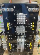
So I switched my annealer over to pulling the induction board gates low to turn the board off - this time with the Schottky diodes (duh). Seems to work just fine based on the limited testing I've done. Much better than switching 48V high current to the induction board. The image below shows the connections (purple and grey wires) to the solder pads of the induction board's R1 and R2 - the sides closest to the board's HEXFETs. I'm pretty sure anyone can manage this mod to the board.
On the other end of these wires I attached the two Schottky diodes (part 1N5818) to isolate the two. Ground these two wires however you see fit (Arduino, controller, Sestos timer) and the board will turn off. No need for an automotive relay etc.
Hi,
Thank you for your help and all you have contributed to this thread.
Please pretend that I'm a second grader. I would like to use your method to control the MOSFETs on the induction board with an arduino signal. So, should I connect the "purple and grey" wires with the diodes directly to positive signal from the arduino pin? Is that what you mean by grounding the wires? Also did you remove the R1 and R2 from the board in this picture? Did you do any mods to the induction board? If so, could you take a picture of the board from the front.
1. I'm not that familiar with Arduino boards and their capabilities so others will have to chime in here as well
2. I see you are using a 'kit'. You will have to understand how the code works for this kit and possibly modify it to have this work properly.
That said, the mod is easy. No modifications to the induction board are needed other than attaching the two wires either at the gates of the induction board HEXFETs or the "right side" (side closest to the HEXFET gates) of R1 and R2 on the induction board as shown in my pics. The Schottky diodes isolate each wire/gate and allow you to use one switch to control them.
You still need a switch - either one built into the Arduino board or a separate one controlled by the Arduino board (depending on the Arduino board capabilities - others chime in here) - to control the gates. To turn the induction board OFF you switch the gates to ground (turn the switch on which connects the gates to ground).
If you need a separate switch (ie the Arduino doesn't have an on-board switch that can be triggered to sink the induction board gates to GND) there are literally tons of options. Selection of a suitable part will depend on (a) what's in stock these days and (b) it has to be able to continuously sink the requisite current continuously (as it sinks this current when the induction board is not annealing, perhaps while you gather your things ready to start annealing).
EDIT: it has to be able to sink 200mA continuously
When the gate of the MOSFET switch is raised high the wires with diodes (in my pic) which are connected to the MOSFET drain terminal are then connected to the source terminal which you wire to GND somewhere convenient. You also need to make sure that the Vgs(th) of the chosen MOSFET is low enough that 5V (Arduino logic level) is enough to turn the switch on. (Vgs(th) is the threshold voltage differential between the gate "g" and the source "s", which is held at 0 volts/GND, that turns the MOSFET on. So Vgs(th) needs to be less than 5V.)
But maybe the Arduino has all this built in so let's get that answered first.
With respect to (2) above, you will need to make sure the code/logic of the Arduino is set up properly. More often we turn a switch on to start a process, ie switch on = begin annealing. (For example, if you used an automotive relay to switch power to the induction board, the Arduino would turn on a switch that allowed 12V current to flow through the automotive relay's coil hence energizing the relay, turning it on and connecting 48V to the induction board.) Here the logic is the opposite. Turn a switch on (which connects the induction board gates to GND) to turn OFF the induction board. Given you are using a kit and not programming the Arduino yourself you may need help changing this logic.
If you are not up for this, simply use an automotive relay such as the one I used previously and have the Arduino switch the flow of current 12V through its work coil. Arduino says switch on and the low side of the relay coil is connected to GDN and 12V current flows through the coil, energizing the relay and connecting 48V to the induction board. Arduino says switch off and the low side of the relay coil is no longer connected to GND, no current can flow and the relay is in a no-connect state and no power is supplied to the induction board. The likely reason your "solid state relay" isn't working is because you are exceeding its safe operating area. This is largely a function of current and the resistance from drain to source when it's in an "on" state. It can't handle the power dissipation and blows. A true relay coupled with controlling the flow of (much lower) current through its work coil avoids this issue.
I've been working on MKNZ arduino based annealer currently. It has been working fine but SSR keep shorting and puts my induction coil in a "runaway train" state. Melted a case or two already. Please excuse my lack of electrical knowledge.
I took advice from another forum and ordered a general purpose 2 gate mechanical relay in order to use the mechanical relay instead of the SSR. The output from the Control board that supplies the SSR is only around 6V. Unfortunately the general purpose relay operates at 12V DC. The General purpose relay is not being tripped. I did check the voltage output from the Control board when I activate the start button and the relay is only getting 6V.
I will reach out to MKNZ but is there a way to use that 6V signal to activate the 12V general purpose relay? Can I use a Boost Converter? Is there any other options?
You have 2 options as a "second grater"
- get new SSR (mosfet based - @BlackICE recomendation )
- get a 5 v relay and use its contacts to drive mechanical contactor (120v my favorite)
A simple MOSFET can control the flow of 12V through its coil.
I no longer use this as I simply pull the induction board gates low to turn it off as described above. No more switching high-current 48V. I switch 200mA of 12V.
A simple MOSFET can control the flow of 12V through its coil.
I no longer use this as I simply pull the induction board gates low to turn it off as described above. No more switching high-current 48V. I switch 200mA of 12V.
@D_Pat does not have 12v signal from his control board (only 5 V is available from Arduino) in order to be able to drive directly the proposed SSR. See "Technical Data Sheet" Coil Data.
A 5v relay would work but better would be a low side MOS switch. You can switch on and off at a much faster frequency. Remember to either use 2 switches or isolate with two diodes before connecting to a single switch.
The most common 328P chip can soure or sink about 30ma, best to keep it less than that maybe >=20ma.
Hello everyone, as recommended by larryd, I'm trying to implement a P-channel MOSFET high side switch in a circuit of mine to connect peripherals and sensors to Vcc, alongside with an N-channel low-side switch for a relay (so that I have used both configurations once). While researching for...
@D_Pat before charging down any path you need to come back re 2 in my post above. There are many ways to skin the cat. Some involve more parts than others.
My SSR died and a cheap replacement didn't work so I'm ready to ditch the SSR. I've got a different board (4 HexFet's) so if I'm following correctly I should connect the G (ground) pins to ground thru the diodes to turn it off? I'm using an Arduino to control the SSR now so will modify that to control the board.
If the configuration is similar to the 2 FET boards, then you have 2.64 uf instead of 1.98 uf. This will cause a coil change if you're still shooting for around 100 khz.
This Forum's expenses are primarily paid by member contributions. You can upgrade your Forum membership in seconds. Gold and Silver members get unlimited FREE classifieds for one year. Gold members can upload custom avatars.
This site uses cookies to help personalise content, tailor your experience and to keep you logged in if you register.
By continuing to use this site, you are consenting to our use of cookies.