
Induction brass annealer redux
- Thread starter Gina1
- Start date


 Also check your wiring. At a rating of 240 volts it should have worked. If I may ask, "where do you get your parts"? Only reason I ask is for me to look over (on-line) what is available. Some times parts get mis-marked and you may have gotten a lower voltage varistor. This has happened to other builders, all different parts.
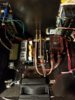
Upgrades & Donations
This Forum's expenses are primarily paid by member contributions. You can upgrade your Forum membership in seconds. Gold and Silver members get unlimited FREE classifieds for one year. Gold members can upload custom avatars.

Click Upgrade Membership Button ABOVE to get Gold or Silver Status.
You can also donate any amount, large or small, with the button below. Include your Forum Name in the PayPal Notes field.
To DONATE by CHECK, or make a recurring donation, CLICK HERE to learn how.
Click Upgrade Membership Button ABOVE to get Gold or Silver Status.
You can also donate any amount, large or small, with the button below. Include your Forum Name in the PayPal Notes field.
To DONATE by CHECK, or make a recurring donation, CLICK HERE to learn how.