Here's some photos of my build, plus some thoughts.
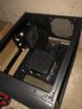
I set out to build the annealer such that it would store in between the supports on my loading bench - that meant it had to be narrower than 14". The net result of that is that the whole layout ended up pretty pretty tight, and I had to revamp things several times along the way. Such is the nature of protoyping, I guess.
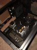
The build is a basic GinaErick with a couple of small modifications. I used a 30A SSR instead of the contactor relay. Given that some folks may have had problems with that route, we'll see how it goes here. I may opt to install a second SSR to switch the negative side of the power supply, too. I'm also looking into implementing Norm's suggestion about putting a capacitor in between the terminals on the inductor board to fix that problem (finding the right cap is proving interesting).
I also used the Meanwell RSP-750-48 power supply, with the thought that I would have the flexibility to experiment with coil sizes later without risk of nuking my supply or inductor board. I haven't wired up current control, yet - and as you can see, I'm only pulling close to 13A right now. The power supply will do 15.7A. I added a 7 position switch and used GrocMax's spreadsheet to calculate the resistor values to put on the switch. All that's left to do is build the connector harness to hook up the control wire from the switch to the power supply.
Also per GrocMax's suggestion, I added 4 heat sinks to the bottom of the induction board. Those do seem to help keep the induction board a little cooler.
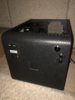
I've said it before, but... my woodworking skills leave a lot to be desired. Of course, I lack great tools, too. I did the whole thing with a SkilSaw, a drill, an impact gun, and a coping saw (which cuts, but basically has a mind of its own). A couple of C-clamps and a ruler allow you to make straight, square-ish cuts w/ the SkilSaw, at least (when you don't screw it up).
With some better tooling and the experience of build #1, I can greatly improve the look, here. But, my fabrication skills are never going to match FishinDog's
")
The net result is... I have a working annealer that takes up an acceptable amount of space under my bench, and didn't cost me an arm and a leg. Plus, I gained some great experience by building it out myself.
Futures ... I might build a new case that doesn't look like I chewed the boards apart. I might work up a smaller coil (3/4" ID instead of 1" ID). I might convert it over to Arduino or something just to gain some experience working with embedded stuff in an appliance environment. For now, I'm just going to anneal some brass and enjoy it!
Thanks to everyone who contributed to this thread (especially Gina, Hollywood, FishinDog, and GrocMax)!!
View attachment 1035213 View attachment 1035214 View attachment 1035215 View attachment 1035216 View attachment 1035217