• This Forum is for adults 18 years of age or over. By continuing to use this Forum you are confirming that you are 18 or older. No content shall be viewed by any person under 18 in California.

Induction brass annealer redux

You're right, I didn't look at your post...today. I did look at it a year and a half ago, and it raised as many questions as it answered for me. I had honestly forgotten about that post, but do remember the numerous times you've casually thrown out the "just take the FETs low", or some variation on that. As a non-EE, that makes about as much sense to me as "just snodfark the flabgass and the sun will come up tomorrow".

The guy whose post I was addressing seemed to want as simple a solution as possible, and I tried to give him that with a minimalist plug-and-play design using off-the-shelf components as much as possible. Will it work for him? Maybe, maybe not, but it doesn't require any detailed modifications or fabrication (other than the coil, and there aren't many ways around that).

Your solution is elegant, I'll give you that, but for me (and maybe a couple others on this forum) low-tech and straightforward, which make it easier to troubleshoot later on, works okay.
 
It's a lot easier to switch 0.2 amps than that running through the ZVS when operating. There's already a relay on the timer module you linked to. A quick Google: http://www.songlerelay.com/Public/Uploads/20161104/581c81ac16e36.pdf
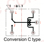
According to the photo on Amazon the relay is of type "conversion C". Therefore you can simply use this existing relay to turn the ZVS board on and off.

You will likely find that the middle wire connection socket - marked "COM" in the diagram on Amazon - is connected to the pin I have labelled "1" on the diagram below (extracted from the data sheet for the relay). The pin I have labelled "2" is likely the one labelled "NC" in the diagram on Amazon. My pin "3" is their "NO". So, when the relay coil is NOT energized (ie it is off) pin 1 is connected to pin 2 and when it is energized (ie the timer turns it on) pin 1 is connected to pin 3.

If the gates of the ZVS board HEXFETs are connected (via Schottky diodes) to Pin 1 of this relay (COM) and Pin 2 (NC) is connected to GND then the ZVS board won't operate. If we leave Pin 3 (NO) unconnected to anything, when the timer energizes the relay the ZVS Board Gates connection to GND is broken when it swings to pin 3 - the ZVS Board will operate.

Just requires a couple of Schottky diodes which are as cheap as chips.

Now, I haven't purchased one of those timers and I am relying on looking at the photographs on Amazon but a quick look at the timer to check the relay part and confirm traces to the connector housing will likely confirm things.

Screenshot 2023-10-20 at 11.05.19 PM.png
 
Hello, I made some test with the annealer sistem but at the First annealing the ZVS board remain activate although the light of the ssr is off.
Only one start and all make a trouble...
Is more suitable use a mecanical relay?
100A 24v?
Can anyone help for solving?
 
Did you use a Chinese SSR? It may have shorted. Their ratings are not reliable.
Indeed the ssr are chinese ...
Rated for 60A DC to DC.
I buyed also the cooling fin ...

At this point I think to use one Classic relay, a mechanical relay, I think to use rated 100A or more for 12v (this voltage for choising the relay are correct?).
The controll voltage of the timer for the relay of zvs is 12V.

Thanks
 
If you use a relay (not Chinese) over spec it and you might consider a snubber across the contacts. Another option is to get a non-Chinese SSR.
 
It is used to suppress arcing across contacts. Do an internet search for relay contact arc suppression. You’ll get lots of info.
 
Hello, I had a dubd, I wired the ssr (power side) likes wiring a mechanical relay, are this wrong?
The ssr wiring Is differenti from the mechanical type wiring?
 
Couldn’t figure out how to display it in English but it looks like severe overkill!
If you use a relay don’t forget to use a diode across the coil. Cathode to plus (+) side.
 
Quite a few will work. 100v PIV (more than enough) and pick a current rating greater than or equal to the coil current.
 
Hello, can anyone link me the type of snubber t'ha I can buy from Amazon or AliExpress?
Of this is necessary in the annealer alimentation circuit.

Thanks
 
Ciao, Bora72,
Lei parla di SSR (Solid State Relay) or Contactor? Ayuda me capire per auydarli :)
He’s referring to a relay/contactor. He first tried a chinese SSR and it failed. I suggested a non Chinese but I think he found them too expensive. I suggested a snubber across the contacts if he was going to use a relay.
 
I used these and haven't had any problems with my ginaerick
Packard C230 2 Pole 30 Amp Contactor, 120 Volt Coil and a 34462 Varistor 130VAC
I'm just not as smart as some of you guys on electronics and the mods you all did are awesome
 

Upgrades & Donations

This Forum's expenses are primarily paid by member contributions. You can upgrade your Forum membership in seconds. Gold and Silver members get unlimited FREE classifieds for one year. Gold members can upload custom avatars.


Click Upgrade Membership Button ABOVE to get Gold or Silver Status.

You can also donate any amount, large or small, with the button below. Include your Forum Name in the PayPal Notes field.


To DONATE by CHECK, or make a recurring donation, CLICK HERE to learn how.

Forum statistics

Threads
165,802
Messages
2,203,621
Members
79,130
Latest member
Jsawyer09
Back
Top