• This Forum is for adults 18 years of age or over. By continuing to use this Forum you are confirming that you are 18 or older. No content shall be viewed by any person under 18 in California.

Induction brass annealer redux

Alright, trouble shooting time and looking for pointers.

I pulled it all apart to isolate the problem.

The problem: when brass is inserted into the induction coil the ZVS board and the PSU lose power then come back when load is removed from the coil.

To find this is the problem I disconnected everything and now have the PSU plugged right into the ZVS.

Faulty ZVS board?

Thanks.
It sounds as if you are saying that the output of the power supply is now connected directly to the ZVS Board. If so, that is a problem.

The power supply must be on and up to voltage before the output is connected to the ZVX Board. That is the reason for using a relay, either mechanical or solid state.
 
It would be helpful to get the current sensor working. You should get a reading with the ZVS on with no brass.
 
It sounds as if you are saying that the output of the power supply is now connected directly to the ZVS Board. If so, that is a problem.

The power supply must be on and up to voltage before the output is connected to the ZVX Board. That is the reason for using a relay, either mechanical or solid state.
I had a SSR attached to begin with. I tried 2 different ones just to rule out the SSR being the problem.

I jacked straight from the PSU to the ZVS to isolate the issue. It's something with the PSU or ZVS, I'm thinking ZVS.

I don't see how having it setup this way would be any issue. There are plenty of people running a ZVS this way.

The PSU and ZVS both are getting power. It's when a load is introduced to the coil that the loss of power happens.
 
Last edited:
A 600 watt 48v supply means only 12.5 amps. Turning down to 44v may not increase the current. Depends on supply design.
12.5 amps seems light. A lot of people have observed more than that with brass in the coil. If that’s your case the supply is going into current limit.
 
The issue with connecting the supply direct to ZVS - the ZVS doesn’t like low voltage possibly causing a shorted fet. If the supply has a soft start feature this would cause the ZVS to see a low voltage as the supply comes up.
 
The issue with connecting the supply direct to ZVS - the ZVS doesn’t like low voltage possibly causing a shorted fet. If the supply has a soft start feature this would cause the ZVS to see a low voltage as the supply comes up.
I used most of the build sheet from https://www.mgnz-makes.com/
and used the same PSU.

With the ZVS connected directly to the PSU the coil heats up. When a load is introduced to the coil it kills it.

I'm using the same spec coil he used as well.

Hooked up to a SSR with no load it gets no power. The LED on the board lightly flickers.

Everything's working but the induction coil. The case feeder is spinning. The dropper is dropping. The switches and LEDs work. (12v supply side all works)

The current sensor reads 0 amps. Which makes since since it's not working.
 
Last edited:
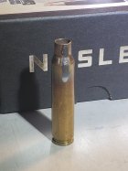
Hello, the knowledge and experience in this thread is amazing, encyclopedic! Wondering if anyone will offer a "quick opinion" on this annealing result, with Tempilaq 850 (my 1000 degree has dried up <frown>).
It's a .223 GFI case (96.5 gr) and I used 4.1 seconds inductive exposure (my annealer is not very powerful).

--> So, question for the veteran induction annealers here: is this distance down the case body looking acceptable, based on your unique experience? Or, does it look like I should go a little further down. Thank you!

TMP-850_4,1-sec.jpg
 
I’m surprised you detect a warm coil. After annealing cases that pull 20 amps my coil feels cool (or at least room temperature) to me.
You need to get the current sensor working as it will help troubleshoot the system.
 
I’m surprised you detect a warm coil. After annealing cases that pull 20 amps my coil feels cool (or at least room temperature) to me.
You need to get the current sensor working as it will help troubleshoot the system.
I had the pump turned off. Yeah, it gets really warm without water circulating and when switched on for more than a few seconds at a time.
 
Think at this point I will get another ZVS and maybe power supply. It's obviously one of those two.

I was just looking for someone that ran into the same issue to trouble shoot as I feel I saw this problem happen before in a post.
 
My first build was a totally different design in kit form from Fluxion so none of that would help. The second build (for a friend) was based on the GinaErik design. I used a 36v, 1,000W supply. Some cases drew just over 20 amps. I also used a US made 100v, 40A SSR. I understand the Chinese ones are questionable. Not built for what they are rated for.
 
I'm not following
I used most of the build sheet from https://www.mgnz-makes.com/
and used the same PSU.

With the ZVS connected directly to the PSU the coil heats up. When a load is introduced to the coil it kills it.

I'm using the same spec coil he used as well.

Hooked up to a SSR with no load it gets no power. The LED on the board lightly flickers.

Everything's working but the induction coil. The case feeder is spinning. The dropper is dropping. The switches and LEDs work. (12v supply side all works)

The current sensor reads 0 amps. Which makes since since it's not working.
I'm sure I'm not understanding you correctly...it sounds like you are powering the ZVS board continuously and dropping a case into a running coil/field. If that is not the case, ignore this. If it is the case, then the problem is that the ZVS board needs to be slammed with full output of a fully powered up power supply.

The ZVS circuit needs that to start the occillation of the field in the coil, otherwise, as has been stated, the relatively slow increase in power output from the power supply as it starts up won't work.

Another way of saying this is the power supply needs to be fully up and running, the ZVS board needs to be completely unpowered, then when the relay is closed to start a heating cycle the full output of the power supply is dumped through the relay into the ZVS board, abruptly starting the field in the coil to begin occilating and the brass to be heated. Then when the heating cycle is over, the relay opens and the ZVS board returns to a completely unpowered state.
 
My first build was a totally different design in kit form from Fluxion so none of that would help. The second build (for a friend) was based on the GinaErik design. I used a 36v, 1,000W supply. Some cases drew just over 20 amps. I also used a US made 100v, 40A SSR. I understand the Chinese ones are questionable. Not built for what they are rated for.
Most of these Chinese electronics are of bad and questionable quality. Reading through this thread, there's lots of bad ZVS boards and SSR's of Chinese origin going around.

I originally preferred a Taiwanese meanwell se-600-48 PSU for this build. Ordered one off eBay months ago that some idiot killed and sold "as new." I sent that one back.
That PSU weighs 5x what this cheap Chinese PSU does.

I just ordered the meanwell se-600-48, this time from a reputable source. I'm going to give that a try. Still could be the ZVS. Going to hold out on ordering a new one tell I test out the new PSU first.

My build won't be so neat looking with the meanwell as it doesn't fit in the case, but I don't care if it works.
 
Hello, the knowledge and experience in this thread is amazing, encyclopedic! Wondering if anyone will offer a "quick opinion" on this annealing result, with Tempilaq 850 (my 1000 degree has dried up <frown>).
It's a .223 GFI case (96.5 gr) and I used 4.1 seconds inductive exposure (my annealer is not very powerful).

--> So, question for the veteran induction annealers here: is this distance down the case body looking acceptable, based on your unique experience? Or, does it look like I should go a little further down. Thank you!

View attachment 1383946
looks fine to me
 
I'm not following

I'm sure I'm not understanding you correctly...it sounds like you are powering the ZVS board continuously and dropping a case into a running coil/field. If that is not the case, ignore this. If it is the case, then the problem is that the ZVS board needs to be slammed with full output of a fully powered up power supply.

The ZVS circuit needs that to start the occillation of the field in the coil, otherwise, as has been stated, the relatively slow increase in power output from the power supply as it starts up won't work.

Another way of saying this is the power supply needs to be fully up and running, the ZVS board needs to be completely unpowered, then when the relay is closed to start a heating cycle the full output of the power supply is dumped through the relay into the ZVS board, abruptly starting the field in the coil to begin occilating and the brass to be heated. Then when the heating cycle is over, the relay opens and the ZVS board returns to a completely unpowered state.
I tried to get it going with 2 Chinese SSR's of different makes. No dice. Wouldn't power the ZVS.

I then plugged the power directly from the PSU to the ZVS board. Power. Coil gets hot. When a load is inserted, poof, 48v PSU and ZVS lose power tell load is removed from the coil.
 
I then plugged the power directly from the PSU to the ZVS board. Power. Coil gets hot. When a load is inserted, poof, 48v PSU and ZVS lose power tell load is removed from the coil.
Do not do that. ZVS needs instant power (must be applied through a relay), in order to start osculating.

Check with an ohm meter the ZVS. If it shows some resistance the board is OK. I smell a bad Power Supply. Most likely if is overloaded, the built-in over current protection shoots the output off - you amp sensor delivers 0 reading.

The reason for overload current is the coil. It is not your case - I see that the turns are insulated and the configuration is very common.

All my experimental PS of 600 watts went directly to the garbage. Try to get 850 watts or bigger. You can try and see how the 44-48 volts goes down to 10-15 volts during load conditions.

Also if you apply DC voltage to ZVS without attached coil, most likely the ZVS would be damaged.

Good luck.
 
Last edited:
I tried to get it going with 2 Chinese SSR's of different makes. No dice. Wouldn't power the ZVS.

I then plugged the power directly from the PSU to the ZVS board. Power. Coil gets hot. When a load is inserted, poof, 48v PSU and ZVS lose power tell load is removed from the coil.
Again, if your letting the ZVS board power up when you turn on the power supply, then its not getting the sudden spike of power to get the circuit to occilate correctly. Whether this is the cause of your issue of losing power in the coil or not, I don't know, just that the ZVS circuit is not designed to gradually power up.

any chance of getting a schematic of your build...doesn't need to be fancy electrical engineer quality (overkill), just show your power source(s), components, and connections.

here is an example of my builds diagram
 
Last edited:
Do not do that. ZVS needs instant power (must be applied through a relay), in order to start osculating.

Check with an ohm meter the ZVS. If it shows some resistance the board is OK. I smell a bad Power Supply. Most likely if is overloaded, the built-in over current protection shoots the output off - you amp sensor delivers 0 reading.

The reason for overload current is the coil. It is not your case - I see that the turns are insulated and the configuration is very common.

All my experimental PS of 600 watts went directly to the garbage. Try to get 850 watts or bigger. You can try and see how the 44-48 volts goes down to 10-15 volts during load conditions.

Also if you apply DC voltage to ZVS without attached coil, most likely the ZVS would be damaged.

Good luck.

Thanks for the advise!

I had this feeling as well and ordered a replacement meanwell PSU. It's also 600w.... But the build quality between these cheap Chinese PSU's and Taiwanese is night and day. Hopefully that one works. If not, I'll step up to higher wattage as I already purchased it.

Thanks everyone for all the advise.


Just to double tap. My 12v line works great, no problem. Control board, switches, case dropper, case feeder. SSR receives signal and the light on the SSR triggers. When that happens the 48v PSU light turns off.

I'll update after I test the new PSU.
 

Upgrades & Donations

This Forum's expenses are primarily paid by member contributions. You can upgrade your Forum membership in seconds. Gold and Silver members get unlimited FREE classifieds for one year. Gold members can upload custom avatars.


Click Upgrade Membership Button ABOVE to get Gold or Silver Status.

You can also donate any amount, large or small, with the button below. Include your Forum Name in the PayPal Notes field.


To DONATE by CHECK, or make a recurring donation, CLICK HERE to learn how.

Forum statistics

Threads
165,795
Messages
2,203,589
Members
79,130
Latest member
Jsawyer09
Back
Top