Once the Curie Temp is reached, current drops.
Does brass have a Curie Temp? I tried to find more info, but it looks like neither Copper or Zinc have an established Curie Point?
Once the Curie Temp is reached, current drops.
Another solution I have seen to the problem of alignment of the case in the coil is to insert a 13mm glass tube ID inside the coil. (Do some tests first to make sure 13mm operates the way that you want it to.) You then drop the case into the tube and it is always aligned. I believe acrylic tube will react poorly to the heat whereas glass is OK. It would assist to have a small funnel of appropriate diameter attached to the top of the tube to make the feeding process easier. As I said in my recent reply above, 223 will work quite well in the 13mm diameter as well.Updated my post, Bruce. Like mentioned above, I'm not a fan of the platform I have now so I'm redesigning it to hopefully get something similar to the traditional trapdoor design. The current design was simpler to make, but ejection puts too much force on the bottom coil, creates a longer footprint needed for the device, and has no means for cartridge centering beyond using your hands.. all in addition to the aforementioned heat issues.
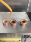
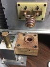
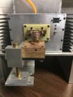
I have a trapdoor design but I made a phenolic bushing with different sized inserts for the various cartridge sizes. it is centered with the trapdoor and coil. With the little bit of wiggle room remaining I notice the case self-centers when the power is turned on. It may be because my coils are smaller in diameter than some I've seen posted.
Can you upload some pictures of the bushing system, this is one thing I'm still not very sure on how to go about doing.I have used the same type of bushings. It is true that the case aligned itself when the magnetic field is present. I noticed this in coil as well as in the ferrite core. The 13 mm pyrex glass tube works very well - it helps the cartridge to land center of the trap door.
Btw What is the inner diameter of your coil? What is the caliber of your brass? Seconds annealing?
Thanks
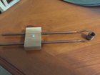
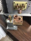
100 page milestone!
What a great thread. Thanks again Gina.

And just a couple more to make 2,000 posts. Magnificent !!Awwww shucks Thank You
P = tMaxAv * (F + K * (tMaxAv-90)*0.1);
F = 0.48;
K = -0.016;
P => proposal in 10/s;
tMaxAv => time max current average in 10/s;
tMaxAv should be in a range from 6 to 13 sec (choose V ZVS accordingly)
Here in Australia we have 240VAC, and if you make a mistake working with that it is often fatal. For that reason I have designed my annealer to run on 48VDC and 12VDC. I have attached below my wiring diagram, which has only taken me about two years to get around to drawing. Mine is auto feed, and is controlled by a case from the auto feed roller passing a proximity sensor as it drops into a funnel and then into the coil. The prox sensor is energised and activates the timer. The timer closes the relay and holds it closed for the set duration (e.g. 5.8 secs). The next timer opens the trapdoor for 0.4 sec and drops the case. Everything then waits for the next case to drop past the prox sensor and start the process again. Hope this is of some assistance to those working with 240VAC.
Hi Gina. I have used a NO NPN inductive sensor with 8mm detecting range from EBay ,Nicely done... What is the part number for the proximity sensor and where did you order it from. Your design is the first I've seen that could trigger the timer. It is something I think I would like to add to my unit (Mod 2, built almost 3 years ago)(+ 5,000 cases and still going strong)
Yes... good decision to go 12 volt for the fans and annealer PCB. I used 110VAC, because it was what I had at the time.
Thank you for sharing
Gina
Cool, how did you come up with the formula?
I just tested it and implemented it in my arduino controlled annealer - seems to work (did a test on a few 308 and a 223 cases and the proposed times are close to what I would have used tempilaq to determine).
AMP has filed a patent application (not granted - yet..) on "Annealing parameter determination". Seems like using the melting point determined by observing current during annealing cycle as a reference point could be a no go...
I don't know for sure yet if it works, but it seems each type of case (variation by brands/manufacturers, caused by trimming, neckturning etc) have their own distinct current draw over time curves, making cases recognizable by just observing the current. It would be possible to use machine learning for case classification and/or anneal time determination - e.g. forecasting anneal time of unknown cases just by observing the current draw for a fraction of a second? Right now I'm thinking of making a tensorflow model, train it with time series data and case labels (from serial logger), and convert it to tensorflow lite to embed to arduino or other microcontroller..
The training part would obviously (unless you control the annealer with a powerfull computer) be done outside the annealer unit which most like would be controlled by a microcontroller (eg arduino). If it works, why not have the model(s) created in the cloud - Anneal Cloud

