• This Forum is for adults 18 years of age or over. By continuing to use this Forum you are confirming that you are 18 or older. No content shall be viewed by any person under 18 in California.

Induction brass annealer redux

Updated my post, Bruce. Like mentioned above, I'm not a fan of the platform I have now so I'm redesigning it to hopefully get something similar to the traditional trapdoor design. The current design was simpler to make, but ejection puts too much force on the bottom coil, creates a longer footprint needed for the device, and has no means for cartridge centering beyond using your hands.. all in addition to the aforementioned heat issues.
Another solution I have seen to the problem of alignment of the case in the coil is to insert a 13mm glass tube ID inside the coil. (Do some tests first to make sure 13mm operates the way that you want it to.) You then drop the case into the tube and it is always aligned. I believe acrylic tube will react poorly to the heat whereas glass is OK. It would assist to have a small funnel of appropriate diameter attached to the top of the tube to make the feeding process easier. As I said in my recent reply above, 223 will work quite well in the 13mm diameter as well.
 
Last edited:
I have a trapdoor design but I made a phenolic bushing with different sized inserts for the various cartridge sizes. it is centered with the trapdoor and coil. With the little bit of wiggle room remaining I notice the case self-centers when the power is turned on. It may be because my coils are smaller in diameter than some I've seen posted.
 
I have some parts coming and will be starting by build as they arrive! I made an attempt at a much simpler version and while it worked, it was taking 18 seconds to anneal a 308 case. After a few PMs with Gina (thank you), I have ordered the parts list almost to a T of what's on the first page. Looking forward to sharing my progress with you guys and gals and probably getting some help along the way.
 
I have a trapdoor design but I made a phenolic bushing with different sized inserts for the various cartridge sizes. it is centered with the trapdoor and coil. With the little bit of wiggle room remaining I notice the case self-centers when the power is turned on. It may be because my coils are smaller in diameter than some I've seen posted.

I have used the same type of bushings. It is true that the case aligned itself when the magnetic field is present. I noticed this in coil as well as in the ferrite core. The 13 mm pyrex glass tube works very well - it helps the cartridge to land center of the trap door.

Btw What is the inner diameter of your coil? What is the caliber of your brass? Seconds annealing?
Thanks
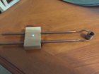
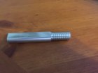
Can you upload some pictures of the bushing system, this is one thing I'm still not very sure on how to go about doing.
 
I have 4 different coils - .485, .530, .580 & .730 ID.

I haven't done any reloading in quite a while so I don't remember what the time was. I am GUESSING but I think .223 was in the 2-4 second range.
I also have 6mm-250, 6x47L and .243AI.

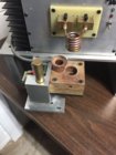
My coil design -
wood block is to keep it intact.
IMG_0965.jpeg

coil winder -
I have 3 other sizes. Friend with a cnc lathe made them for me.
IMG_0966.jpeg

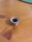
Phenolic adapter -
IMG_0967.jpeg
The phenolic piece that this sits in has an optical sensor that the case trips to start annealing. Trap door opens for as long as the case blocks the sensor, plus a little.
 
An adapter (out of place) -
IMG_0968.jpeg
Ignore the color of the coil. I had a turn or two touching.

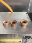
3 inserts -
IMG_0969.jpeg
They are tapered to assist feeding. Never had one hang up.

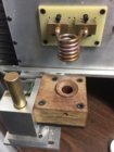
Insert in place -
IMG_0970.jpeg

The front -
IMG_0972.jpeg

The phenolic assembly is adjustable vertically, horizontally and front to back. The timer is set to 2.00 seconds.
The aluminum behind the hose is the water tank. WAY bigger than I needed but at the time I didn't know what I'd need and I didn't want to make it again if it was too small.
 
Just done 100 Lapua cases I sized down from 308 to 6.5CM. First cases it was pulling 13 amps right before it timed out at 6.2 seconds. A bit later I noticed it was down to 12.9 amps so I got the Templik out and tested a case. It seemed fine so I carried on. Didn’t take a whole lot of notice but at about case 85 it was only just pulling 11.9 to 12 amps. Painted a case and it didn’t turn as far down the case at the 1st one I checked.
Meanwell 750w supply. I think there’s a pic of it back at post 1000. It’s pretty much configured as per the build list in Gina’s first posts.
Has anyone else noticed this?
 
Here in Australia we have 240VAC, and if you make a mistake working with that it is often fatal. For that reason I have designed my annealer to run on 48VDC and 12VDC. I have attached below my wiring diagram, which has only taken me about two years to get around to drawing. Mine is auto feed, and is controlled by a case from the auto feed roller passing a proximity sensor as it drops into a funnel and then into the coil. The prox sensor is energised and activates the timer. The timer closes the relay and holds it closed for the set duration (e.g. 5.8 secs). The next timer opens the trapdoor for 0.4 sec and drops the case. Everything then waits for the next case to drop past the prox sensor and start the process again. Hope this is of some assistance to those working with 240VAC.

Induction Annealer Cabling Plan.jpg
 

Attachments

Last edited:
P = tMaxAv * (F + K * (tMaxAv-90)*0.1);

F = 0.48;
K = -0.016;
P => proposal in 10/s;
tMaxAv => time max current average in 10/s;

tMaxAv should be in a range from 6 to 13 sec (choose V ZVS accordingly)

Cool, how did you come up with the formula?
I just tested it and implemented it in my arduino controlled annealer - seems to work (did a test on a few 308 and a 223 cases and the proposed times are close to what I would have used tempilaq to determine).

AMP has filed a patent application (not granted - yet..) on "Annealing parameter determination". Seems like using the melting point determined by observing current during annealing cycle as a reference point could be a no go...

I don't know for sure yet if it works, but it seems each type of case (variation by brands/manufacturers, caused by trimming, neckturning etc) have their own distinct current draw over time curves, making cases recognizable by just observing the current. It would be possible to use machine learning for case classification and/or anneal time determination - e.g. forecasting anneal time of unknown cases just by observing the current draw for a fraction of a second? Right now I'm thinking of making a tensorflow model, train it with time series data and case labels (from serial logger), and convert it to tensorflow lite to embed to arduino or other microcontroller..
The training part would obviously (unless you control the annealer with a powerfull computer) be done outside the annealer unit which most like would be controlled by a microcontroller (eg arduino). If it works, why not have the model(s) created in the cloud - Anneal Cloud ;)
 
Man
You guys are way too smart for this dumb frog
I love reading all the different ways you all built the annealer
Me I just went with the old standby design with 1 mod
I replaced the 12 amp ps with a 20 amp ps
Keep up the the improvements it's great reading about them
 
Here in Australia we have 240VAC, and if you make a mistake working with that it is often fatal. For that reason I have designed my annealer to run on 48VDC and 12VDC. I have attached below my wiring diagram, which has only taken me about two years to get around to drawing. Mine is auto feed, and is controlled by a case from the auto feed roller passing a proximity sensor as it drops into a funnel and then into the coil. The prox sensor is energised and activates the timer. The timer closes the relay and holds it closed for the set duration (e.g. 5.8 secs). The next timer opens the trapdoor for 0.4 sec and drops the case. Everything then waits for the next case to drop past the prox sensor and start the process again. Hope this is of some assistance to those working with 240VAC.

Nicely done... What is the part number for the proximity sensor and where did you order it from. Your design is the first I've seen that could trigger the timer. It is something I think I would like to add to my unit (Mod 2, built almost 3 years ago)(+ 5,000 cases and still going strong)
Yes... good decision to go 12 volt for the fans and annealer PCB. I used 110VAC, because it was what I had at the time.
Thank you for sharing
Gina
Hi Gina. I have used a NO NPN inductive sensor with 8mm detecting range from EBay ,

DC 6-36V Wire Inductive Proximity Sensor Detection Switch NPN LJ18A3-8-Z/BX - $AU17.52


but I think this compacitive sensor with 10mm detection range (from EBay) would be better.

DC 6-36V NPN NO 3-Wire Capacitive Proximity Sensor Switch 10mm LJC18A3-B-Z / BX - $AU18.46


What I would be after with the second one is particularly the 10mm detection range, as I have had the very occasional 223 case slip past the sensor without activating it. Either inductive or capacitive is fine but NOT magnetic, as our brass cases have zero magnetic qualities and will not energise the sensor. Inductive sense metal objects and capacitive sense any object, so they will both work quite well with brass cases.

Whatever you get, read the specifications very carefully. It needs to be Normally Open (NO for the benefit of other readers) so the passing case will close it and activate the signal. Also, preference is for the longest detection range you can find - 4mm is a waste of time, my current 8mm is good 99% of the time, but I think 10mm would be 100% reliable.

With the part number LJ18A3-8-Z/BX the -8- part usually indicates detection range in this case 8mm, so -4- would be 4mm and so on. That seems to work most of the time. But then the capacitive one listed above has -B- and is 10mm. What that means in this item is anyone's guess.

You then need to work out how you are going to get the cases to consistently pass and activate the sensor. As mentioned above I used a funnel and cut the sensor into the back of the neck of it, but you could just as easily have the cases roll across the face of the sensor. The possibilities are endless.

Bruce
 
Last edited:
Why not optical? I suppose it depends on the construction of the unit. I used optical in the base where the case sits during heating. I used a microcontroller (PIC) which uses the optical as an input to turn on the annealer for the time selected on the thumbwheel switches.
 
Cool, how did you come up with the formula?
I just tested it and implemented it in my arduino controlled annealer - seems to work (did a test on a few 308 and a 223 cases and the proposed times are close to what I would have used tempilaq to determine).

I'm curious on same - obviously, times too short or long are going to interfere with the formula, but I don't think we run into that problem in practice.

AMP has filed a patent application (not granted - yet..) on "Annealing parameter determination". Seems like using the melting point determined by observing current during annealing cycle as a reference point could be a no go...

How would that patent prevent us from using it privately? Using a patented invention for research, education, etc, without commercializing it is generally considered fine and legal. Plus... the damages for one of us using it are, at most, the cost of an AMP unit. A lawsuit to pursue that is waaaay more than that. Perhaps providing a pre-made kit with the code for someone to buy would be a bit over the line, but that's not happening here. This is very much DIY for personal use only.

On a different note, the patent refers to monitoring resonant frequency of the induction circuit (something I don't think we can directly do on the GinaErick hardware as currently spec'ed - but I'm a dummy.. LOL) - and then mentions current flow as almost an afterthought. That allows it to be covered by the patent, but in practice I wonder if current draw is maybe not what they're using.

Also - smart patent. They're setting it up to cover large scale industrial processes, too, which might pay dividends for them later!

I don't know for sure yet if it works, but it seems each type of case (variation by brands/manufacturers, caused by trimming, neckturning etc) have their own distinct current draw over time curves, making cases recognizable by just observing the current. It would be possible to use machine learning for case classification and/or anneal time determination - e.g. forecasting anneal time of unknown cases just by observing the current draw for a fraction of a second? Right now I'm thinking of making a tensorflow model, train it with time series data and case labels (from serial logger), and convert it to tensorflow lite to embed to arduino or other microcontroller..
The training part would obviously (unless you control the annealer with a powerfull computer) be done outside the annealer unit which most like would be controlled by a microcontroller (eg arduino). If it works, why not have the model(s) created in the cloud - Anneal Cloud ;)

This would also be cool, if you can work it out! Keep us posted - I'd love to learn more about how you go about it!
 

Upgrades & Donations

This Forum's expenses are primarily paid by member contributions. You can upgrade your Forum membership in seconds. Gold and Silver members get unlimited FREE classifieds for one year. Gold members can upload custom avatars.


Click Upgrade Membership Button ABOVE to get Gold or Silver Status.

You can also donate any amount, large or small, with the button below. Include your Forum Name in the PayPal Notes field.


To DONATE by CHECK, or make a recurring donation, CLICK HERE to learn how.

Forum statistics

Threads
165,780
Messages
2,203,257
Members
79,110
Latest member
miles813
Back
Top