Hey all, here's my version of the GinaErick Induction Annealer... it's nowhere as advanced as some of the other designs I've had the pleasure of reading about!!
First off, a huge
thank you to Gina1 and Hollywood for making the idea of this design public, and especially to Gina for being so accessible for consultation. Secondly, I owe the inspiration of my design
heavily to dabeechman's design (which can be found here
http://forum.accurateshooter.com/th...-annealer-redux.3908353/page-41#post-37147086 and
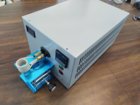
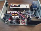
http://forum.accurateshooter.com/th...-annealer-redux.3908353/page-42#post-37147479) which I found very appealing for its compactness. I was able to find an enclosure, the
Hammond 1416o, that matched almost perfectly.
Somethings I did differently included utilizing compression fittings for the reducing union between the 1/8" coil and 1/4" tubing, and using 1/4" compression x 5/16" barb fittings to attach to the coolant loop; the coolant loop only utilizes 5/16 vinyl tubing. I haven't noticed any adverse effects from the large brass fittings (yet!), and coolant flow seems more than sufficient. The 1/8" compression fitting does theoretically allow me to swap coils and drain fluid with relative ease.
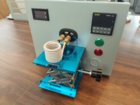
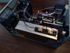
However, though it works fine mechanically, I'm not happy with the elevator and ejector system I have at the moment; the aluminum base absorbs too much heat and subsequently heats up the solenoid over extended use. I'll try to find another solution utilizing corian squares I have on the way.
Otherwise, it was a fantastic experience building this device (over the last several months

) considering I was a complete novice in things electrical and building. This was one heck of a first electronic project to say the least.. but now I've got new tools and knowledge for the future

Hopefully this inspires other inexperienced readers on the fence to go for it!
I'd be happy to answer questions to the best of my ability, and my parts list is on hand if you're interested.
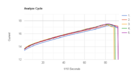
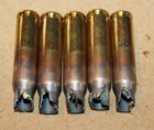
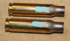
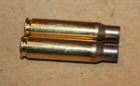
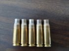
Here's a demonstration of it in action by over-annealing a .223 case