Follow along with the video below to see how to install our site as a web app on your home screen.
Note: This feature may not be available in some browsers.
This Forum is for adults 18 years of age or over. By continuing to use this Forum you are confirming that you are 18 or older. No content shall be viewed by any person under 18 in California.
I'm new to all this I started my annealer before seeing this sight but have struggled getting it to work properly. After reading through this have solved a lot of my problems like coil size and so on. My current problem is on my amp meter I'm showing 14amp at 40.6v with nothing in the coil. When I add a piece of brass to the coil it ramps to 22amps. Something doesn't seem right to me I have read that others people have had the same problem but couldn't find anything that fixed mine.
Dont have any metal within 2in of the coil. If any one has any suggestions please let me know.
1000w zvs board
48v 20A 1000W power supply
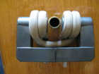
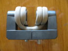
I would like to see a front view of your coil. If your running the coil through a mental case, and the coil is close (in/out) close to the case you may be inducing current into the sheet metal of your of your case, hence the extra current. further looking at your picture, I can't tell if the base below your coil is metal or plastic. Metal would cause higher current readings.
The front platform is all plastic with a pyrex glass tube for positioning the only parts that are metal are the sides of the computer case.Thanks for the quick response you guys have done wonders for the home built annealer.
Not that I know of, I wrapped them close together then went back through and spread them apart but after dipping them in the lacquer they seemed like they might have pulled together when it dried but I would think there would still be lacquer between them. I will investigate further.
Looks like you have the right answer, I just went back to where I bought the voltage gauge and found instructions you have to set the display to the 50amp shunt otherwise it's set up for the 100amp.
It would have been nice if they sent instructions with it. I will give this a try and get back to let everyone know if this worked.
I really would like to have the coil would around a tube that can take inserts to center the case. As the case top needs to be below the top of the coil I would really appreciate some ideas on this area of the build.
Not needed. The case just needs to settle in the right place. Just have inserts that fit and adjust the shelf hole in which they settle. Have them chamfered so that you are not narrowing the "target aperture" for the drop. I can throw a case in from quite a distance away and so long as it goes inside the top of the work coil (i.e. I don't miss completely) the case will settle centred in the coil.
The modifications for the board you mention are unlikely to get you anywhere. You can model the circuit in LTspice to check power requirements for individual parts. You will very likely find things are suitably oversized already. Regarding capacitors, the challenge is finding parts the fit the footprint of the existing board. If you are designing the board from scratch then you have freedom to choose. Space them out, some on top, some on the bottom. If you are using the existing board I wouldn't bother. Upgrade if things break.
The current board I have is not the same design it is not the 50A but it had a fan and the component rating were not as per shown in the 20A board. So it is more for repair than any intended upgrade as such. I will blow up a board again I know it I am a tinkerer and will start trying things with stuff jerry rigged before it gets all put together nicely.
I take your point and I think thats sort of the way I would go if I go with the coil just a short base maybe 1/4 case high with funnel but have it so it can insert into pyrex tube that the coil would be wrapped around. so the different bases would bit in the bottom shelf with trap door below.
Decided to edit the table a bit since I changed my plans on the table again... Gonna use 2 stepper motors with linear screw rods to move the table up and down because why not.
The 1800w induction board is much heavier duty board with two large fans and big heat sinks. I can run pretty much 100% duty cycle at 900 watts. Highly recommended if you want to run faster cycles.
Decided to edit the table a bit since I changed my plans on the table again... Gonna use 2 stepper motors with linear screw rods to move the table up and down because why not.
That looks like a "transverse induction flux coil." Not sure what the function of the ferrite rods are. Ferrite beads or collars are usually used to kill high frequency ripple on a power supply. I understand that such flux coils are normally used to heat long/flat thin work pieces where the distance from the work piece surface to the work coil isn't consistent. I've no idea whether their advantages with respect to that application have any benefits here where we have a cylindrical work piece with (if centred properly) a consistent distance between its surface and a cylindrical work coil. You will have to let us know how you get on. It is pretty simple to wrap copper tubing around a suitable mandrel and get an effective work coil.
I watched a few tutorials and such and caught on pretty quickly. Once you understand how the software works it's pretty easy, even doing off plane stuff. The software is also very forgiving if you just need to reorganized the order you've built things or just go back and change something. I typically turn or the origin and sketches when working.
Yes, doing things like the shelf is very easy. The only mildly hard part of that was projecting faces for the inserts. The model for the autofeeder was more challenging. There the angle of the hopper can be changed and all the other geometry (e.g. the shape of the drop shoot) updates/changes accordingly. I think the software is really amazing and fascinating.
I was thinking of using a stepper motor, but with a spinning disk that had holes in it so you could just spin the disk and the case would drop, then soon a little more to close. Depending on size of disk to keep motor away from coil, you could have maybe 8 or so alternating hole/solid pairs.
This Forum's expenses are primarily paid by member contributions. You can upgrade your Forum membership in seconds. Gold and Silver members get unlimited FREE classifieds for one year. Gold members can upload custom avatars.
This site uses cookies to help personalise content, tailor your experience and to keep you logged in if you register.
By continuing to use this site, you are consenting to our use of cookies.


")