
Install the app
How to install the app on iOS
Follow along with the video below to see how to install our site as a web app on your home screen.
Note: This feature may not be available in some browsers.
You are using an out of date browser. It may not display this or other websites correctly.
You should upgrade or use an alternative browser.
You should upgrade or use an alternative browser.
Induction brass annealer redux
- Thread starter Gina1
- Start date


Only the drop over the wiring from the PSU to the wherever the sense wire is attached. Normally this would be right at the load. If it is anywhere else the drop from that point to the load is not compensated for. In this application I don't think it is worth the hassle.
The Sestos timer "manual" isn't clear which supply pin needs to be +12V and which at GND when the device is powered from 12VDC. Anyone know which way around they should be before I have a guess?
The Sestos timer "manual" isn't clear which supply pin needs to be +12V and which at GND when the device is powered from 12VDC. Anyone know which way around they should be before I have a guess?

First of all I want to say its great to find this forum where Gina and Hollywood posted their how-to for the annealer, then see how people have joined in with tweaks and improvements, and all along the group answers questions to help everyone understand the details needed to complete their particular build. I've been lurking here awhile, wanting to read all this great info and absorb it before I asked some question that's already been well covered. I think I'm at about 90% comprehension, so there's still a bit to go, but I'm up to speed enough that I think I can contribute some ideas for potential improvement that come from my particular areas of expertise and experience. Basic electrical theory I'm ok, with electronics I can plug and play, however when its gets to circuit theory I can understand a conversation I hear, but sometime my understanding is at that "enough to be dangerous" level. On the flip side I'm very mechanically inclined, and when I see new things always look to see "how it works", so I've got a lot of years of mentally inventorying away little tidbits of details of how machines work. Plus I've got lots of experience seeing how mechanical things go wrong, and how to tweak things to make them work better next time around.
I happen to have a lot of experience in industrial heat exchange and pumping systems, and it seems with the early GinaEric design, its 600W power supply and hand being fed, the little self contained pump and reservoir worked fine, but as more people go to higher wattage power supplies and especially adding on the auto feeders, cooling starts to become a limitation. I haven't built my system yet, so I can't give you any data to support my ideas, but I will suggest what improvements should give best bang for the buck. Also please let me be clear, I'm not at all bashing the original design. It worked great and its a decent price. but for those who want more cooling capacity for whatever reason I have some suggestions.
The coil with the 1/8" tubing gives a lot of resistance to flow. The only reference to a measured flowrate through the closed loop in the basic design that I recall seeing was by Gina. She'd measured 1/2 cup (4 ounces I presume) in a minute. That's 0.03 gpm or just under 2 gph (gallons/hr), not much flow. Lol on these little pumps I thnk they generally rate them in gph instead of gpm to make the number look bigger. Almost all these inexpensive pumps in this size and flow range are open impeller centrifugal pumps. Its because they're by far cheaper to make, and can be fairly reliable for the cost. The only flowrate related spec on the GinaEric partslist pump I saw was 1.9m and that's not flow, but head. Head is a measure of how much pressure the pump can overcome, and the units are in terms of height of a vertical column of water, and in this case 1.9m is 1.9 meters. To put it in terms more people can relate to, that's roughly 2.7 psi. With centrifugal pumps flow and head have a inversely proportional non-linear relationship. It may be closer to linear in the middle of the performance range, but gets steep on the ends. On an industrial pump you'd buy, the manufacturer would supply a flow versus head graph that had overlayed HP requirement lines. Unfortunately we don't have a curve for this pump. In my experience if you're only given a head spec for a pump, that's the pressure at which the flow drops to zero, so your system pressure drop (resistance) must be lower than that to get ANY flow at all. Electrical people can kinda think of a pump as a wierd, fixed watt power supply. If the piping system attached to the pump has a lot of resistance or ohms (friction from turbulence of going through small tubing), then it takes more volts (head pressure) to get your flow. and since you have limited watts available, your amperage (flowrate) is reduced. Ok, ok its vaguely similar.
Ok now that we're all up to speed on pump flow characteristics, I will say that I bet there is someone who's seen how much flow that little pump can do if you just point the outlet hose back into the top of the reservoir (without passing through the coil and heat exchanger. I'll wager its 3 or 4 times as much as Gina measured going though both the coil and the heat exchanger. What's happening is we're operating this little pump way to one end of its performance curve, so we don't get much flow.
The other way to increase cooling capacity of the system is to improve performance of the existing heat exchanger (radiator). Heat exchangers in general are relatively high pressure drop compared to the piping system they're installed in, and in fact if you don't have enough flow though them to the point that there IS significant pressure drop, then you're operating them on the LOW end of their performance curve. What I'm saying is that on a gpm basis, you transfer more heat from the water to the air when the water flows fast than when it goes slow. Heat exchangers need turbulent flow to conduct the heat from the body of the water stream through the wall of the tubing to the cooling medium on other side (air in our case). For a given heat load a system with an oversized heat exchanger will reject less heat than one with a properly sized heat exchanger. Its not intuitive, but this is one of those rare situations where bigger isn't better.
Its really a challenge for this one pump to give us sufficient flow through two high resistance items in series.
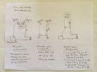
So now that we understand the issues, we can come up with improvements. There are several ways to approach it. If you've got the original pump with integral reservoir and aren't ready to start over, I'd suggest buying a small centrifugal pump that has both inlet and outlet connections and hose barb connections that matches your current tubing size at your radiator. There are some on ebay that are sold as solar circulating pumps for less than $10. https://www.ebay.com/itm/DC12V-3M-2...ersible-Pool-Water-Pump-Solar-56/253130755697 You'll also need two tubing tee's and a couple of extra feet of tubing. See the attached sketch for more detail, but you basically create a recirculation loop around just the radiator that is in series with the original pump and coil. This increases the velocity of the water going through the radiator improving its overall heat transfer, and at same time reducing the head that the original pump feels. The latter shifts the operating point of the pump on its flow vs head curve towards an incrementally higher flow. The combination of the two will increase the flow through the coil and improve the heat rejected at the radiator, so if running at the same cartridge per minute rate the steady state water temperature will be lower than before.
The other option if you had built a reservoir using an external pump, you can add a second pump that will circulate just to the radiator and back. The original pump that went to the coil can be rerouted to come straight back to the reservoir, bypassing the radiator. There are some small submersible pumps sold on ebay for around $10 that are closer to 5m head ( https://www.ebay.com/itm/Newest-DC-...bmersible-Immersible-Pump-Shower/122863803456 ), so if your reservoir has enough internal space for it, you can add one of those. The system might perform better with the 5m one feeding the coil.
Hope you managed to stay awake until the end of this, and if you've got any questions feel free to ask.
The coil with the 1/8" tubing gives a lot of resistance to flow. The only reference to a measured flowrate through the closed loop in the basic design that I recall seeing was by Gina. She'd measured 1/2 cup (4 ounces I presume) in a minute. That's 0.03 gpm or just under 2 gph (gallons/hr), not much flow. Lol on these little pumps I thnk they generally rate them in gph instead of gpm to make the number look bigger. Almost all these inexpensive pumps in this size and flow range are open impeller centrifugal pumps. Its because they're by far cheaper to make, and can be fairly reliable for the cost. The only flowrate related spec on the GinaEric partslist pump I saw was 1.9m and that's not flow, but head. Head is a measure of how much pressure the pump can overcome, and the units are in terms of height of a vertical column of water, and in this case 1.9m is 1.9 meters. To put it in terms more people can relate to, that's roughly 2.7 psi. With centrifugal pumps flow and head have a inversely proportional non-linear relationship. It may be closer to linear in the middle of the performance range, but gets steep on the ends. On an industrial pump you'd buy, the manufacturer would supply a flow versus head graph that had overlayed HP requirement lines. Unfortunately we don't have a curve for this pump. In my experience if you're only given a head spec for a pump, that's the pressure at which the flow drops to zero, so your system pressure drop (resistance) must be lower than that to get ANY flow at all. Electrical people can kinda think of a pump as a wierd, fixed watt power supply. If the piping system attached to the pump has a lot of resistance or ohms (friction from turbulence of going through small tubing), then it takes more volts (head pressure) to get your flow. and since you have limited watts available, your amperage (flowrate) is reduced. Ok, ok its vaguely similar.
Ok now that we're all up to speed on pump flow characteristics, I will say that I bet there is someone who's seen how much flow that little pump can do if you just point the outlet hose back into the top of the reservoir (without passing through the coil and heat exchanger. I'll wager its 3 or 4 times as much as Gina measured going though both the coil and the heat exchanger. What's happening is we're operating this little pump way to one end of its performance curve, so we don't get much flow.
The other way to increase cooling capacity of the system is to improve performance of the existing heat exchanger (radiator). Heat exchangers in general are relatively high pressure drop compared to the piping system they're installed in, and in fact if you don't have enough flow though them to the point that there IS significant pressure drop, then you're operating them on the LOW end of their performance curve. What I'm saying is that on a gpm basis, you transfer more heat from the water to the air when the water flows fast than when it goes slow. Heat exchangers need turbulent flow to conduct the heat from the body of the water stream through the wall of the tubing to the cooling medium on other side (air in our case). For a given heat load a system with an oversized heat exchanger will reject less heat than one with a properly sized heat exchanger. Its not intuitive, but this is one of those rare situations where bigger isn't better.
Its really a challenge for this one pump to give us sufficient flow through two high resistance items in series.
So now that we understand the issues, we can come up with improvements. There are several ways to approach it. If you've got the original pump with integral reservoir and aren't ready to start over, I'd suggest buying a small centrifugal pump that has both inlet and outlet connections and hose barb connections that matches your current tubing size at your radiator. There are some on ebay that are sold as solar circulating pumps for less than $10. https://www.ebay.com/itm/DC12V-3M-2...ersible-Pool-Water-Pump-Solar-56/253130755697 You'll also need two tubing tee's and a couple of extra feet of tubing. See the attached sketch for more detail, but you basically create a recirculation loop around just the radiator that is in series with the original pump and coil. This increases the velocity of the water going through the radiator improving its overall heat transfer, and at same time reducing the head that the original pump feels. The latter shifts the operating point of the pump on its flow vs head curve towards an incrementally higher flow. The combination of the two will increase the flow through the coil and improve the heat rejected at the radiator, so if running at the same cartridge per minute rate the steady state water temperature will be lower than before.
The other option if you had built a reservoir using an external pump, you can add a second pump that will circulate just to the radiator and back. The original pump that went to the coil can be rerouted to come straight back to the reservoir, bypassing the radiator. There are some small submersible pumps sold on ebay for around $10 that are closer to 5m head ( https://www.ebay.com/itm/Newest-DC-...bmersible-Immersible-Pump-Shower/122863803456 ), so if your reservoir has enough internal space for it, you can add one of those. The system might perform better with the 5m one feeding the coil.
Hope you managed to stay awake until the end of this, and if you've got any questions feel free to ask.
Attachments
Thanks Grocmax. I got it right first guess. I think we have more or less the same wiring. I switched V+ to the induction board rather than GND return leg. Plus your shunt wiring code doesn't match the guidance here:
https://i.ebayimg.com/images/g/J7UAAOSw~QRaRIhV/s-l1600.jpg
I assume they changed the wiring colouring since you got yours. In the ones you buy now the voltage sense wire is thin yellow. I was also going to place the voltage sense wire at the load/induction board rather than at the PSU so it should read 0V when power isn't being applied to the induction board.
@BillK55 Good stuff. I very nearly bought a larger version of the little aquarium pump that's on the various BoM lists for this very reason. I note also that this is an area where the EZ Anneal did a better job: a larger reservoir for starters and, by the looks of things, a more powerful separate pump. (If you browse the Alphacool website you will see a few of their parts.)
In the end I just went with the flow ('scuse the pun) and stuck to the little guy. I don't have a lot of space in my enclosure. What I did do was minimise any narrow tubing. In post 1 or 2 of this thread Gina shows a transition method to go from 3/8" ID tubing to 1/4" ID. I routed everything with 3/8" ID tubing and merely slipped a clamp-width section of 1/4" ID plastic tubing over the end of the 1/4" copper that passes across the induction board. (No need for the separate copper transitions.) It looks like the EZ Anneal may have gone for thicker coil tubing as well. Also they appear to have a longer coil, i.e. more turns, which would provide greater induction (more turns = more henrys) and quicker annealing times, potentially meaning less heat transfer from the hot cases to the fluid in the surrounding coil.
@ottsm probably has the best data on the cooling system. He is actually measuring the flow rate: 5.5 gph according to his video. He is also measuring the temperature of the coolant (albeit with a thermistor strapped to the plastic tubing rather than something with better heat transfer). I'm not sure which pump he is using and of course his results will depend on how he has coupled it all together plus his fan setup.
At the end of the day, however, much of the heat in this system isn't really in the coil. Unlike a computer system where one is trying to suck heat from, say, the CPU, here the hot part is ejected from the system through the trap door. It releases most of its heat sitting in a tray somewhere. We have two elements which require some cooling: (1) the heat generated from the induction board capacitors and diodes and (2) heat transferred to the coil from the induction process. (1) is dealt with by fan circulation of air. Re (2) annoyingly the cheapo induction boards are very poorly laid out and pass copper tubing straight over the top of the hot capacitors**. If annealing times are relatively quick the hot case is ejected before being able to transfer a lot of heat over the air gap between it and the coil. So there's less reliance on the liquid cooling system. At the end of the day, if the coil isn't getting too hot you're golden.
I added Insultherm to my coils for two reasons: one, I could get a tighter coil with bare copper tubing (no enamel insulation) without fear of shorting a coil loop and, two, to reduce heat transfer from the heating case to the coil. I reckon it is worth the extra several bucks. (It also looks good.)
I still think a better place for optimisation is the induction board itself. It's not a complicated board and is about as basic as it gets for this application. I'm not surprised that the EZ Anneal folks seem to have made their own.
** I am going to wrap some Kapton tape over the copper tubing in this area.
Last edited:
One other thing for people to think about. The most expensive component for someone wanting current limiting in the builds to date is the cost of the Mean Well 48V PSU. Yet current limiting is very basic to implement. We really don't even need variable control - just a fixed limit. A little piece of protoboard and a half dozen components costing cents would get you all you need.
Just one more thing... ") while talking about improvements, who's up for adding an infrared sensor to their coil to monitor the temperature of the case using the black body temperature effect? No more Tempilaq. Enter the desired temperature and have the controller eject the case when it hits target temp!
while talking about improvements, who's up for adding an infrared sensor to their coil to monitor the temperature of the case using the black body temperature effect? No more Tempilaq. Enter the desired temperature and have the controller eject the case when it hits target temp!
while talking about improvements, who's up for adding an infrared sensor to their coil to monitor the temperature of the case using the black body temperature effect? No more Tempilaq. Enter the desired temperature and have the controller eject the case when it hits target temp!Interesting !!Just one more thing...
Not sure how that would work, as for me, my cases (6BR-Dasher) sit well into the coil.
I anneal down to about 1/4" below the shoulder. Since the case is below the top of the coil, there would be no line of sight to the shoulder area to check temp.
Although, if the sensor were attached to the inside of the coil, at the right position, 1/4" below the shoulder, it could work. Would the eddy currents from the inductor board cause a problem, being that the sensor is inside the coil?
Last edited:
Therein lies the design challenge. My post was a little in jest. Most examples you will see around the net use something like the MLX90614 which integrates the thermopile detector and the signal conditioning processor. We are focused on a relatively narrow area of the case. I guess one could get line of sight from the top edge of the coil to the case shoulder. I'm not sure of the 'field of view' of these devices. Anyway, I would put something like this last on the 'design improvement list' well behind a better induction board and simple PSU current limiting (roughly speaking, we more than tripled the cost of the PSU to get current limiting which could be done with about 5 components).
I'd like to seek the input of people here, particularly with regard to the following:
2. The aperture in the tray/dish. The design needs to work for .223 and up. So the aperture needs to be well less than 45mm in width and it seems the balance point for most cases is circa 14-16mm from the head. So I have selected an aperture of 25mm/1" in width.
Boy this feels like a very small aperture...
The tipping point for 300 Win Mag is about 21mm. I'm wondering if it is hanging 21mm over the edge of a 25mm aperture can it topple down? On the other side, the .223 Rem is 45mm in length and a tipping point of say, 16mm. The case neck needs to be over the other side before there's just 16mm left on the other side. So that leaves an error margin of just 4mm if the aperture is 25mm wide.
Any thoughts?
I'd like to know if anyone has used any of the power supplies referenced by Ross Tait back in May 2018. Its a China based Ebay seller onyou2101 and they sell a wide variety of voltage and amp ratings, all significantly cheaper than any other I've seen on ebay. https://www.ebay.com/itm/142462540092 They are a BIG volume ebay seller, over a million items sold. I wrote the seller and over a week ago got a reply saying they would forward my question about whether or not it had a fan to the right dept. Still nothing back.
Its one of those ebay pages where they have lots of V vs A models to choose from, so not as many pics of each model. Near the bottom of the listing there are some pictures where they brag about how theirs are better than others, and there are some pics of internals. Can anyone recognize a fan in there? Would you trust an 800 or 1000w PS with no case fan? For the price they ask I guess I can add a fan.
They offer a 48V 1000w model for $62. It doesn't have the constant current control feature of the RSP-750-48, but from what I understand of how you control the annealing process with the basic design coil, with 20A capacity at 48v would I need to worry about exceeding the current rating?
Boy this feels like a very small aperture...
So that leaves an error margin of just 4mm if the aperture is 25mm wide.
Any thoughts?
Are you talking about the length of the slot in the spinning plate that catches the case, or the opening in the stationary drum? From my understanding of watching a bunch of them on youtube, the slot in the stationary drum is longer than the slot in the plate that carries the case up to the drop point. The lower hole can have plenty of lengthwise clearance over your longest possible case. As long as your slot in the spinning plate has enough length-wise clearance (plus margin of safety) so it doesn't snag as it "tips" (think of the length of case as measured on longitudinal diagonal), you should drop ok. If I'm following your question correctly, then I'd think 4mm excess for the longest possible case should be good. Also remember that your spinning plate has finite thickness, and there will also be a slight gap between the plate and the drum, so as soon as that top forward case reaches the start of the opening in the drum, it will start angling down, even before it goes far enough over the opening to "tip over" and fall.
Some builders will have multiple spinning plates they can swap out if there is so much difference in length of cases, that their shortest case is not well over half of their longest. You don't want two of your short size cases to get picked up in a spinning plate optimized for a long case.
I'm talking about the opening in the stationary hopper (in the model it is called the tray). It's a balancing act - if you will excuse the pun (which will become clear in a moment). The opening's width needs to be shorter than the smallest case. Picture a case that fell into the spinning feeder disc the wrong way around - it is coming towards the hopper opening mouth first. We don't want it to fall through the opening mouth first and so the mouth needs to be supported by the other side of the hopper opening before the case is extended over the other side more than its tipping point. Dangle an empty 223 Rem case (no primer) off the side of your desk and it will not fall so long as more than circa 15mm of the head end is on the desk. So a 45mm .223 Rem case coming the wrong way can just pass an aperture of 45-15=30mm without falling mouth first. It continues support at the neck end until the case head goes over the edge and it topples 'backwards', the right way down the shoot. So how much safety margin? My initial 25mm aperture seems a bit short for 308 Win. It's tipping point is also about 15mm from the case head. I got the occasional jam in testing today (albeit holding the hopper in my hands rather than supported at 30 degrees). The base didn't complete the arc downwards fast enough for the mouth to clear the edge of feeder disc and it got jammed between there and the far side of the hopper opening. The speed of the motor is likely a factor also (I'm using 5rpm). So I'm going to try reducing my 5mm safety margin (driven by .223 Rem as the smallest case).
Yes, there needs to be a feeder disc for each 'class' of calibers. There are quite a few cases in the 12 x 47-52mm range. One disc can cover those. I cocked up my demo feeder disc. I forgot to take account of the fact that the circumference of my feeder disc is 1/4" less than the width of the hopper. I keyed the indentations off this smaller dimension. Of course when the disc is in the hopper the clearance for a case to sit in is from the indented edge of the feeder disc to the wall of the hopper. That 1/4" error (and perhaps too much slop anyway) allowed two 308 cases to sit only just aside each other in a slot.
Other than that I did manage to drill to drill 7 holes in the hopper in the right spots. So it could have been worse.
I'd like to know if anyone has used any of the power supplies referenced by Ross Tait back in May 2018. Its a China based Ebay seller onyou2101 and they sell a wide variety of voltage and amp ratings, all significantly cheaper than any other I've seen on ebay. https://www.ebay.com/itm/142462540092 They are a BIG volume ebay seller, over a million items sold. I wrote the seller and over a week ago got a reply saying they would forward my question about whether or not it had a fan to the right dept. Still nothing back.
Its one of those ebay pages where they have lots of V vs A models to choose from, so not as many pics of each model. Near the bottom of the listing there are some pictures where they brag about how theirs are better than others, and there are some pics of internals. Can anyone recognize a fan in there? Would you trust an 800 or 1000w PS with no case fan? For the price they ask I guess I can add a fan.
They offer a 48V 1000w model for $62. It doesn't have the constant current control feature of the RSP-750-48, but from what I understand of how you control the annealing process with the basic design coil, with 20A capacity at 48v would I need to worry about exceeding the current rating?
I am sure with that high of an output, it would have to have a fan. I only have a 600W, but it looks just like the one shown in the eBay listing (down to sticker placement) and the fan is in the back.
Jdne5b
Gold $$ Contributor
What about an adjustable opening?I'm talking about the opening in the stationary hopper (in the model it is called the tray). It's a balancing act - if you will excuse the pun (which will become clear in a moment). The opening's width needs to be shorter than the smallest case. Picture a case that fell into the spinning feeder disc the wrong way around - it is coming towards the hopper opening mouth first. We don't want it to fall through the opening mouth first and so the mouth needs to be supported by the other side of the hopper opening before the case is extended over the other side more than its tipping point. Dangle an empty 223 Rem case (no primer) off the side of your desk and it will not fall so long as more than circa 15mm of the head end is on the desk. So a 45mm .223 Rem case coming the wrong way can just pass an aperture of 45-15=30mm without falling mouth first. It continues support at the neck end until the case head goes over the edge and it topples 'backwards', the right way down the shoot. So how much safety margin? My initial 25mm aperture seems a bit short for 308 Win. It's tipping point is also about 15mm from the case head. I got the occasional jam in testing today (albeit holding the hopper in my hands rather than supported at 30 degrees). The base didn't complete the arc downwards fast enough for the mouth to clear the edge of feeder disc and it got jammed between there and the far side of the hopper opening. The speed of the motor is likely a factor also (I'm using 5rpm). So I'm going to try reducing my 5mm safety margin (driven by .223 Rem as the smallest case).
Yes, there needs to be a feeder disc for each 'class' of calibers. There are quite a few cases in the 12 x 47-52mm range. One disc can cover those. I cocked up my demo feeder disc. I forgot to take account of the fact that the circumference of my feeder disc is 1/4" less than the width of the hopper. I keyed the indentations off this smaller dimension. Of course when the disc is in the hopper the clearance for a case to sit in is from the indented edge of the feeder disc to the wall of the hopper. That 1/4" error (and perhaps too much slop anyway) allowed two 308 cases to sit only just aside each other in a slot.
Other than that I did manage to drill to drill 7 holes in the hopper in the right spots. So it could have been worse.
They offer a 48V 1000w model for $62. It doesn't have the constant current control feature of the RSP-750-48, but from what I understand of how you control the annealing process with the basic design coil, with 20A capacity at 48v would I need to worry about exceeding the current rating?
In my view the current limiter is just a safety precaution. (Just because the PSU is rated at 20A doesn't mean it won't exceed that and then blow.) But you can do your own current limiter. I don't think you need a programmable limit. Set the limit by design and leave it alone. Wiki has a good example. You need a pass transistor that can handle the current etc but that wouldn't be too hard to figure out. (I'm just stuck trying to finish my own stuff to give it more attention at the moment but there are some much-more-talented-than-me former EEs here who may help.)
EDIT:
"Working Temperature: 0~40℃"
That's rather low...
Last edited:
What about an adjustable opening?
It can't have a seam anywhere that a case would catch (and don't forget the underside will not be accessible). Somewhere in the 25-30m is the magic number. I'll get it by whittling away...
In my view the current limiter is just a safety precaution. (Just because the PSU is rated at 20A doesn't mean it won't exceed that and then blow.) But you can do your own current limiter.
EDIT:
"Working Temperature: 0~40℃"
That's rather low...
Yes I caught that 40℃ too. I'm not likely to be using it anywhere its that hot, but that limit definitely points to it not being industrial grade. The smaller watt PS's on that page all show cases with perforated metal tops to give good convective cooling, but the larger ones are all solid tops, which would LOGICALLY imply there's a fan on the back for front to back air flow. I did check the seller's negative feedback and didn't see any complaints about these PS's.
I'm going to wait til the seller replies back to confirm the fan, or someone here pipes up saying they have one and its fine
Similar threads
- Replies
- 74
- Views
- 47,356
- Replies
- 0
- Views
- 1,576
Upgrades & Donations
This Forum's expenses are primarily paid by member contributions. You can upgrade your Forum membership in seconds. Gold and Silver members get unlimited FREE classifieds for one year. Gold members can upload custom avatars.

Click Upgrade Membership Button ABOVE to get Gold or Silver Status.
You can also donate any amount, large or small, with the button below. Include your Forum Name in the PayPal Notes field.
To DONATE by CHECK, or make a recurring donation, CLICK HERE to learn how.
Click Upgrade Membership Button ABOVE to get Gold or Silver Status.
You can also donate any amount, large or small, with the button below. Include your Forum Name in the PayPal Notes field.
To DONATE by CHECK, or make a recurring donation, CLICK HERE to learn how.