Follow along with the video below to see how to install our site as a web app on your home screen.
Note: This feature may not be available in some browsers.
This Forum is for adults 18 years of age or over. By continuing to use this Forum you are confirming that you are 18 or older. No content shall be viewed by any person under 18 in California.
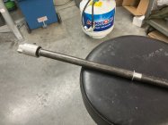
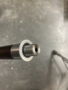
And with my big lathe I need to extend the barrel so I use the muzzle threads and a Parker sealing washer with the rotary union threaded in the other end with another sealing washer. I can now use an out board spider on the extension
My two cents, and I don't know anything so take it for what it's worth. I put the filter between the tank and pump inlet. There WILL be chips and little crap in the tank... I didn't want that going through the pump.
I was worried these pumps dont suck as hard and the blow. They will draw through the filter and not have any problems? I have another 200 micron filter in the drain system but can reroute it easy enough.
My carbonator pump sucks through a 10 micron diesel filter just fine. It'll put out 10x the pressure we need for the job. You could shoot the tailstock off the far end of the lathe if you were so inclined.
My two cents, and I don't know anything so take it for what it's worth. I put the filter between the tank and pump inlet. There WILL be chips and little crap in the tank... I didn't want that going through the pump.
Valid point, but I think it's relative to the oil/coolant reservoir and type of pump used. In your setup, you've set it up on the suction side. I'm actually surprised that even works and doesn't overly restrict the gravity flow back into your reservoir. I'm getting ready to increase to a 1" line out of the catch basin because 3/4" with the viscosity of the dark oil doesn't allow for as much flow as I want.
In my case, the reservoir is a baffled coolant tank, and there isn't enough flow volume through it that would prevent the small chips (all the big stuff is filtered out in the catch basin before it even hits the drain) from settling into the first chamber as they're designed to do. I use a simple utility pump with a buna rubber impeller that's pretty bulletproof, any tiny "chips" that somehow may not have settled out won't hurt it.
Looking for some help with Procon or Procon type pump. Going to ask before making other mistakes. Which is the correct Procon pump, the one with or without a bypass?
In addition to the correct Procon pump, pressure or flow -- not sure of correct termonoligy is controlled by a manual valve. @WSnyder in post #417 posted an example. What happens to oil that is not getting past the valve? Is that bad for the pump or is that the purpose of the internal bypass?
I think the answer is to find a Procon pump with bypass and a manual valve of some type to restrict flow to get the pressure/flow I want to flush chips past reamer and out of the chamber. Is that kinda right?
Valid point, but I think it's relative to the oil/coolant reservoir and type of pump used. In your setup, you've set it up on the suction side. I'm actually surprised that even works and doesn't overly restrict the gravity flow back into your reservoir. I'm getting ready to increase to a 1" line out of the catch basin because 3/4" with the viscosity of the dark oil doesn't allow for as much flow as I want.
In my case, the reservoir is a baffled coolant tank, and there isn't enough flow volume through it that would prevent the small chips (all the big stuff is filtered out in the catch basin before it even hits the drain) from settling into the first chamber as they're designed to do. I use a simple utility pump with a buna rubber impeller that's pretty bulletproof, any tiny "chips" that somehow may not have settled out won't hurt it.
You're probably fine. No baffles in my tank. I stuck a bunch of rare earth magnets on the bottom. I checked my filter after 20 chambers and there isn't a spec in there... But there is for sure a pile of goop in the bottom of the tank where the magnets are. At some point I'll empty the tank and flush it out with mineral spirits or something.
Looking for some help with Procon or Procon type pump. Going to ask before making other mistakes. Which is the correct Procon pump, the one with or without a bypass?
In addition to the correct Procon pump, pressure or flow -- not sure of correct termonoligy is controlled by a manual valve. @WSnyder in post #417 posted an example. What happens to oil that is not getting past the valve? Is that bad for the pump or is that the purpose of the internal bypass?
I think the answer is to find a Procon pump with bypass and a manual valve of some type to restrict flow to get the pressure/flow I want to flush chips past reamer and out of the chamber. Is that kinda right?
Pump, relief valve, needle seat valve to regulate flow rate,
t piece with pressure gauge, ball valve for coolant isolation, t piece with ball valve and air connection fitting for air flush.
Fluid runs into a pan with magnets. Return hose from pan goes into the BOTTOM of the coolant tub and the suction draws from the top of the tub keeps the pump free if debris without needing filters.
A $50 diaphragm sprayer pump will handle a lot of $#!+ and give you plenty of pressure. Just pick one that has enough flow.
I saw way back that you mentioned a part number on that procon pump. Please verify it for me again. There are a number of PSI range and GPH range ones. I think yours was the 250 psi and 125 gph or 2.08 gpm. I see some as high as 4 gpm. Mine is not a procon and actually a two piece cast iron unit bolted together and has developed a leak at the seam. I would rather replace it with the brass procon.
^^^ what is the “needle seat valve” for? Seems redundant. You can adjust the pressure relief valve and throttle down or open up the flow with the ball valve.
^^^ what is the “needle seat valve” for? Seems redundant. You can adjust the pressure relief valve and throttle down or open up the flow with the ball valve.
Ball valves are very poor at metering adjustment. Yes you can do without it but I find it easier to adjust the needle valve to the flow rate required and leave it alone as much as possible. When your want to start and stop your process thats when you swing the ball valve. When you open the ball valve again the needle valve is still providing the exact same flow rate as before.
I've seen these bypass valves mentioned being used in some of the systems. Is one necessarily needed if your using one of the ProCon carbonator pumps with built in adjustable relief valve?
Shop Apollo Valves Conbraco By-Pass Relief Valve 250 Max psi, Bronze 16-501-25 - 37011921 by Penn Tool Co., your trusted partner for quality tools. Join the professionals who trust Penn Tool Co.upgrade now!
No but you have to change the spring in the carbonator pump, so that it will relieve at a lower pressure. Otherwise you might split a filter/housing or blow a hose off when you deadhead the pump. The pump will provide maximum flow until you start cutting and the reamer is blocking the flow path. I have mine set to bypass at 60 psig. So it happily provides cutting oil thru the barrel to the reamer until the reamer is fully engaged in cutting. The flow will drop to a trickle and the pump will be bypassing at 60 psig. When you retract the reamer, full flow again and pump output pressure may drop to 5 psig, I then turn pump off and give it a blast of air. This really blows the chips off. Repeat a time or 2 and go back to cutting.
No needle valves, no external relief valve. I do have ball valves for isolation but not for flow control.
You can close a valve and have 60 psig and 0 flow. No they are not thru coolant reamers, they are piloted reamers with notches cut in the screw, no they don't have coolant bushings on them. I would say the same as 98% are using. When the pilot is engaged, the reamer is cutting full body length and the shoulder. It isn't going to flowing like the Amazon river.
This Forum's expenses are primarily paid by member contributions. You can upgrade your Forum membership in seconds. Gold and Silver members get unlimited FREE classifieds for one year. Gold members can upload custom avatars.
This site uses cookies to help personalise content, tailor your experience and to keep you logged in if you register.
By continuing to use this site, you are consenting to our use of cookies.