• This Forum is for adults 18 years of age or over. By continuing to use this Forum you are confirming that you are 18 or older. No content shall be viewed by any person under 18 in California.

Induction brass annealer redux

Ok then just be aware, as you likely are, you will need to either use a relay to provide 12V to the modified board (ahead of the current limiting resistors eg 1kR) in the "on" state or pull the gates low (on the other side of the resistors) to achieve an "off" state with a MOSFET or similar. You can't use a MOSFET to high-side switch as the gates stay high in their "on" state. If you've done your own board that ought to make sense. Hopefully!

I was looking at this myself today. My control board has a MOSFET that currently just triggers the Sestos timer in one-shot mode. For me to use this to control a modified induction board I need to pull the two gates low and sink the 2 x 12mA for as long as I want to induction board off. And I need to make sure this is within the SOA of the device.

I want to stress to anyone reading that none of the foregoing is relevant to someone using the Sestos as it uses physical relays.

PS: it's been so long since I programmed my PIC that I'm scratching my head over some of the code I wrote!
 
The high end commercial induction annealer has a ferrite air core says it does not use a work coil. How hard would it be to make and not use water to cook the work coil?
 
It still has a “work coil.” It’s wires wrap around an air gapped ferrite core. The induction currents flow in the core and ‘hop’ across the gap into which a case can be placed. Some people here are doing exactly this.
 
It still has a “work coil.” It’s wires wrap around an air gapped ferrite core. The induction currents flow in the core and ‘hop’ across the gap into which a case can be placed. Some people here are doing exactly this.
Ok. If anyone has some pics I would be interested in seeing them, I’m interested in being able to run mine without water
 
If I was to do it all again I would buy the fluxeon unit or just the fluxeon air gaped part. And fit that to your design. Cutting the ferrite and making the litz wire coil with lugs to connect to the board is a PITA


Last edited:
If I was to do it all again I would buy the fluxeon unit or just the fluxeon air gaped part. And fit that to your design. Cutting the ferrite and making the litz wire coil with lugs to connect to the board is a PITA


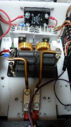
Fluxeon is it. Regarding Litz wires I successfully replaced them with solid copper and a lot easier with Battery Wires. They get hot as much as the Litz on the core. If your duty cycle is reasonable 50% you can run them for ever, provided a direct good fan. Works for me.
 

Attachments

  • Arizona.jpg
    Arizona.jpg
    362.3 KB · Views: 78
  • Arizona1.jpg
    Arizona1.jpg
    341.1 KB · Views: 77
  • Colorado.jpg
    Colorado.jpg
    339.4 KB · Views: 75
I would think that the fluxeon air gaped magnetic field isn't as uniform and symetric as a round coil concentric with the case. Could this lead to uneven heating of the case?

I'm working on putting all the great ideas of this thread all together, but using a tightly magnet wire wrapped dual helix air cooled coil. I have yet to test it with mulitple cases but it does couple more effeciently than most other coils that use 1/8" water cooled tubing. Worst case the duty cycle will be low to keep the coils from compromising the magnet wire's insulation and melting the plastic parts.

Plan to use
1. Auto case feeder using gear motor and hall effect sensor for positioning.
2. Servo controlled drop gate.
3. Flame sensor.
4. ZVS input current sensor.
5. IR or themocouple coil temp sensor.
6. Input power control of ZVS board by controlling its 2 MOSFETs.

Worst case the duty cycle will be extremely low to keep the temp in check, but with the auto case feeder NBD and no need for water cooling.
 
Fluxeon is it. Regarding Litz wires I successfully replaced them with solid copper and a lot easier with Battery Wires. They get hot as much as the Litz on the core. If your duty cycle is reasonable 50% you can run them for ever, provided a direct good fan. Works for me.
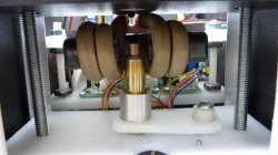
@oliverpsmile is that a fluxeon coil in your second photo. Something else i did was to desolder the middle bank of capacitors and reattach on the other side. Just to help with cooling.
 
I would think that the fluxeon air gaped magnetic field isn't as uniform and symetric as a round coil concentric with the case. Could this lead to uneven heating of the case?
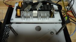
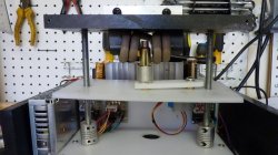
If you position the case every time at the same place you have guaranteed consistency (see the mechanics on the picture). The annealed uniformity of the neck depends on the time under the magnetic field and the thickness of the neck walls. Both factors are favorable - there is an ample time and little heat resistance for the exchange of the uneven heat. Besides less that +/- 50 degrees F (I can imagine bigger difference is possible) is considered acceptable.

I use 3 step motors in my mechanics. The two lift up and down the case platform. They are programmed to stop at the same place for different calibers. The third motor moves the case for annealing at the same place every time, then moves it to a hall for drop out and back for the next case.

The IR sensor for Arizona is installed into the upper black plate above the case (see the plate on the picture, not the sensor). In Colorado, the sensor will be installed 90 degrees toward the neck on a special bracket.

I divide my shooting time between Arizona and Colorado. The Arizona anealer stays in AZ, Colorado will stay in Colorado.
 

Attachments

  • Colorado1.jpg
    Colorado1.jpg
    334.6 KB · Views: 45
Last edited:
@oliverpsmile is that a fluxeon coil in your second photo. Something else i did was to desolder the middle bank of capacitors and reattach on the other side. Just to help with cooling.
Yes it is. Ordered it as a replacement part.
Hi CFM fans are installed on the top of my ZVS-Fluxeon assembly. The cooler the better - I never considered to control the fans.
 
I would think that the fluxeon air gaped magnetic field isn't as uniform and symetric as a round coil concentric with the case. Could this lead to uneven heating of the case?

It's a mistake to view the coil as projecting energy 'from all sides' of the case. If you look at any images/graphics of how flux hops across an air-gapped ferrite core you will see there is plenty of area for the case to sit in and still be enveloped by the flux field. The concentration of flux lines in the core and then across the air gap makes for a much more efficient work coil.

Incidentally I was running my annealer flat out last night with 223 Rem cases. 3.9s and as fast as I could feed them (I didn't bother to set up my feeder). (Figure 3.9s anneal on, 0.65s trap door open to drop the case, 0.5-1s to feed a case, 1.5s for it to settle and then anneal again.) Eventually I hit the limit of how long and fast I could go at about 95 cases. The trap door solenoid was extremely hot and wouldn't work until it cooled. Temps around the induction board and my coolant remained comfortably below my 'overheating' threshold of 70C.
I had a choice of solenoid or servo motor for the trap door. Since the parts cost was almost the same and less 3d printed parts were needed for the servo version I made that one. Solenoid move violently and consume a lot of power on the on state. You should shorten the .65s to something like .3s or less should be enough.
 
FWIW
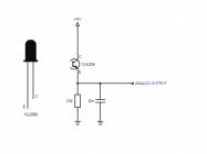
I used a solenoid but I used the “case present” optical sensor to determine how long to leave the solenoid on. After heating is done I have a tight loop looking at the state of that optical sensor. When it changes state I add a little more time for it to clear the trap door hardware then turn solenoid off. This way it only stays on for as long as it has to. Basically 2 lines of Assembly code.
 
Yes. Thanks. When I expand my PIC functionality to remove the Sestos Timer I can use the optical sensor to define how long the trap door is open. Good tip!
 
FWIW... I've really had a lot of fun with this project! But... I'm moving to an AMP. If anyone out there is interested in getting started, I'd be happy to sell off my major components "as is" (power supplies, induction board, coils, pump, relays, Sestos timer, volt/amp meter, radiator) if someone wants spin up on the project. The only difference between my gear and Gina's original spec is that I used an SSR instead of the contactor. My original SSR failed recently - I have a replacement for it on hand, but honestly, I'd just use a contactor moving forward. Keep it simple.

Side note... my SSR failed closed (don't know if that's normal or not), but it was intermittent, and by the time I figured out what was happening, I completely cooked 1 case, and I have probably 2 more floating around a batch of 150-ish cases that I'm not sure about... and I'm not sure what to do about it. That was the sort of my "final straw" that drove me to jump on the AMP bandwagon, not concerns about quality of annealing or anything. But, this is why I'm saying I'd go contactor should I do it again - I think it was greater reliability.
 

Upgrades & Donations

This Forum's expenses are primarily paid by member contributions. You can upgrade your Forum membership in seconds. Gold and Silver members get unlimited FREE classifieds for one year. Gold members can upload custom avatars.


Click Upgrade Membership Button ABOVE to get Gold or Silver Status.

You can also donate any amount, large or small, with the button below. Include your Forum Name in the PayPal Notes field.


To DONATE by CHECK, or make a recurring donation, CLICK HERE to learn how.

Forum statistics

Threads
165,839
Messages
2,203,998
Members
79,148
Latest member
tsteinmetz
Back
Top