Follow along with the video below to see how to install our site as a web app on your home screen.
Note: This feature may not be available in some browsers.
This Forum is for adults 18 years of age or over. By continuing to use this Forum you are confirming that you are 18 or older. No content shall be viewed by any person under 18 in California.
Not sure I follow. In the original build a timer relay is switching another relay to switch 48V. Far simpler to use the relay to switch the 12V to the induction board FETs. Less switches in the on/off path. Less components needed. Next to no current to switch. Very easy mod to induction board.
Hmm the graphic worked yesterday. But no matter. The point that McFred highlighted - and it was one of those "couldn't see the wood for the trees" moments - was that there are already two suitably spec'd and well-heatsinked** switches on the induction board. Control the gates of the IRFP260N and you control the board. All that's required is "breaking the trace(s)" as marked in red in the attached. (If there is 0V at the red cross nothing happens.) If you use 12V or lower (it just needs to exceed the Vgsth of the IRFP260N) you don't even need D1 and D2 nor R1 and R2 (although protection resistors would still be advisable in case an IRF blows). In this case the only current is that passing through the gate bleed resistors R3 and R4 (as the gates of the IRFP260N draw no current) which is just a few milliamps. The low sides of R1/R2 (removed - see points marked in green) provide an ideal entry point for 12V from the timer or even 5V from a logic device (Arduino etc). (You could also amend the LED wiring so that it lights when the gates have power rather than when the 48V is connected which would be all the time.) These are very easy mods to the board.
I'm using an automotive relay in my build as I did not think of this at the time. It's rated for 12V (or 24V ? can't remember) even though I'm using it to switch 48V. When it fails I will do the above modifications to simply have the Sestos timer control the board directly.
** Remember a solid state switch such as a MOSFET has a resistance which creates heat, it's RdsOn. Something people forget about when deploying a SS switch. If RdsOn is high or current high - or both - the amount of heat that needs to be dissipated can be high and inadequate heat sinking will lead to components failure.
...and for those of us without Electrical Engineering degrees...we use the parts we always have as a plug-and-play solution...
but just out of curiosity, could you show us a pic of the actual ZVS board (the one you're using, anyway) that you marked up in an editor with the locations and components you're are talking about...
I would think incorporating an optpcoupler between an arduino and the induction board would be wise so that if the induction board goes south the arduino would be protected.
LOL you don't need an EE degree. I don't have one. R1 and R2 are the big white resistors with 470R and 5W written down the side. My board is installed and so I can't see the traces on the underside of the board but it will be easy to see which side of each is connected to the MOSFET.
I would think incorporating an optpcoupler between an arduino and the induction board would be wise so that if the induction board goes south the arduino would be protected.
Hmm the graphic worked yesterday. But no matter. The point that McFred highlighted - and it was one of those "couldn't see the wood for the trees" moments - was that there are already two suitably spec'd and well-heatsinked** switches on the induction board. Control the gates of the IRFP260N and you control the board. All that's required is "breaking the trace(s)" as marked in red in the attached. (If there is 0V at the red cross nothing happens.) If you use 12V or lower (it just needs to exceed the Vgsth of the IRFP260N) you don't even need D1 and D2 nor R1 and R2 (although protection resistors would still be advisable in case an IRF blows). In this case the only current is that passing through the gate bleed resistors R3 and R4 (as the gates of the IRFP260N draw no current) which is just a few milliamps. The low sides of R1/R2 (removed - see points marked in green) provide an ideal entry point for 12V from the timer or even 5V from a logic device (Arduino etc). (You could also amend the LED wiring so that it lights when the gates have power rather than when the 48V is connected which would be all the time.) These are very easy mods to the board.
I'm using an automotive relay in my build as I did not think of this at the time. It's rated for 12V (or 24V ? can't remember) even though I'm using it to switch 48V. When it fails I will do the above modifications to simply have the Sestos timer control the board directly.
** Remember a solid state switch such as a MOSFET has a resistance which creates heat, it's RdsOn. Something people forget about when deploying a SS switch. If RdsOn is high or current high - or both - the amount of heat that needs to be dissipated can be high and inadequate heat sinking will lead to components failure.
Interesting mod... I guess it would be up to the individual builder to use it or not. Makes since to use it if the builder knows what they are doing. As one of the posters here said it would have been useful to have a picture of the bottom inductor board showing where the trace is cut and how the connection is brought out. BTW what voltage is used to drive the FET's ?
Gina
Removing the big resistors provides a tap in point without having to cut a trace.
you can see from the circuit that the voltage at the MOSFET gates is limited to 12v by the two zeners to ensure the gate-source voltage Vgs doesn't exceed its max of 20V. 5V would be enough for the FETs to turn on (Vgs(th) is max 4V) is leaving open the possibility of driving the board from a logic level device.
SGK...
Again this mod, although it looks good ( one big bravo) and will save on parts cost, it may not be for all builders.
Over the past five + years I have walked countless builders that have had almost no electronics experience, helping them build their units..
Modifying the inductor board maybe, more then they would understand, So for the basic GinaErick anealer.
I would go with KISS, unless they knew what they were doing.
Just my humble opinion
Gina
The sound of the click of a contactor/relay is a happy confirmation that your built is working properly. The Solid State devices are good, provided that they are guaranteed to work realiably. My 12 SSR-s malfunctioned 2 times in a row in ON position. As a result I had several plastic parts melted. In my latest built I use a $60 SSR , switching several times ON/OFF per second, but I kept the the contactor in series - sort of insurance.
That's what you get when you try to switch a big load rather than switching a small one. (Although my automotive relay has never failed.) By all means use a physical relay to switch the 12V - the Sestos timer used in the original build has two of them.
The induction board has two high quality SSR on it.
Fifth Generation HEXFETs from International Rectifier utilize advanced processing techniques to achieve extremely low on- resistance per silicon area. This benefit, combined with the fast switching speed and ruggedized device design that HEXFET Power MOSFETs are well known for, provides the designer with an extremely efficient and reliable device for use in a wide variety of applications.
LOL you don't need an EE degree. I don't have one. R1 and R2 are the big white resistors with 470R and 5W written down the side. My board is installed and so I can't see the traces on the underside of the board but it will be easy to see which side of each is connected to the MOSFET.
I took another look at my annealer today. While you can't see them in the photo, with good light you can clearly see the traces along the top of the board from R1/R2 to the gates of Q1 and Q2. The gate on an IRFP260N is pin 1 - the leftmost pin. So, using the image above, if looking from the right side towards the HEXFETs mounted on the back of the heatsinks, pin 1 the gate is on the left. You will see a trace from each of the large white resistors connecting, on one side, R1, D1 and R3 and the gate of Q1 and, on the other (top) side of the board, R2, D2, R4 and the gate of Q2.
R1 and R2 can easily be removed, carefully, with two soldering irons (one on each leg of the resistor on the underside of the board) or with one iron and flooding solder so that both pads are heated. Gravity or gentle help from a third hand will allow the resistors to fall out when their pins are loose. Clean up with a little solder wick. If you don't damage the board traces you can always put the resistors back if desired.
Once removed, and again looking from the top of the board as above, the now empty pads closest to Q1 and Q2 are your entry points for 12v. I would connect a basic 1k ohm resistor between the pad and the 12V from the timer to limit current in the event of a fault in the FET. Such resistors are only a few cents each. (If the gate of the FET shorts to ground for some reason only 12mA will flow through the gate and that should be fine for the timer. In such case, not much power is dissipated so you won't need more than a 1/4W resistor.) The 1kR resistor and the 10kR resistor create a voltage divider but there's still plenty of voltage to drive the FET gate. You could go higher than 1k so long as there's at least 4V at the gate of Q1/Q2. (Adjust accordingly if driving the FETs via a logic level device.)
Now your Sestos timer, or whatever you are using, need only switch 12V with very little current draw across the switch. Both FET gates need to be driven from the same switch. Timer "on" and its relay connects 12V to the induction board. Timer "off" and the 12V is disconnected. The 48V remains connected permanently. No current can flow through the work coil if the both the FETs are "off".
Edit: I marked up the photo to show the rough position of each trace
The inexpensive Amazon SSR's are junk and most agree that they are not actually built to the specs advertised.
I have a 48V/1000W power supply, and I use a double pole mechanical relay so that I can use 12V to actuate the relay and switch both the positive and negative poles from the 48V power supply to the ZVS board.
URBEST 8 Pin JQX-12F 2Z DC 12V 30A DPDT General Purpose Power Relay for Remote Control, Automatic Control System: Amazon.com: Industrial & Scientific
www.amazon.com
This is the one I've been using, and although it shows the switching to be limited to 250V AC / 28V DC, it is 30 Amps. So far, I have had no issues with 48V and about 15-20 Amps.
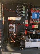
Just to put the above mod into perspective, the "switch" shown in the attached photo could turn the induction board on and off (and pulse its output if asked to).
When I developed my little 'control board' I had no prior experience at programming them nor in writing in C. I did the bare minimum to achieve what I wanted which was: measuring temperature at various places within the case, and scaling the spin rate of two fans via PWM accordingly; detect a case in the work coil and start the Sestos timer; and to control power to my auto feeder. I should have persevered a bit more and used the PIC to control the time of the anneal (ie turn the induction board on and off) and to control the trap door solenoid, i.e. to completely remove the need for the Sestos timer. I may well do that now. (I think I even have two unused I/O pins which could be used with a flame sensor but will have to check.)
*****
You can think of a PIC microcontroller as a little single-chip Arduino. Not nearly as powerful and without the input/output pins already on an Arduino board but capable of doing all we need here. You have to build a board for them. A shortcoming of an Arduino board is you may well have to build a daughter board to accommodate additional components (eg the resistors and capacitors needed to measure temperature or switches such as to control power supply). The advantage is they have a lot more functionality (if needed), I/O pins already on the board and there's a bunch of expansion add-ins available off the shelf. Plus they're ready made and relatively cheap. I'm not sure if programming is easier, but the language is similar. If I were starting from scratch now I'd use an Arduino board if only because I might hope my son gets a liking to programming and creating Arduino projects rather than playing Roblox or Minecraft!
Here's a pic of the top side if the populated board. (There are a bunch of SMD components on the underside as well.) It's 5cm square. The PIC microcontroller isn't installed in the pic but you can see the slot for the through hole component.You can clearly see "switch 1" which is controlling power to my auto feeder. The empty "switch 2" could control the 'modified' induction board. SesTimer could perhaps be reconfigured to control the trap door solenoid.
Has anyone used the BERM BRM-40DD SSR? Just wondering if they have a failure rate similar to the other chycom units.
I’m considering doing the McFred mod but not there yet.
This Forum's expenses are primarily paid by member contributions. You can upgrade your Forum membership in seconds. Gold and Silver members get unlimited FREE classifieds for one year. Gold members can upload custom avatars.
This site uses cookies to help personalise content, tailor your experience and to keep you logged in if you register.
By continuing to use this site, you are consenting to our use of cookies.