Install the app
How to install the app on iOS
Follow along with the video below to see how to install our site as a web app on your home screen.
Note: This feature may not be available in some browsers.
You are using an out of date browser. It may not display this or other websites correctly.
You should upgrade or use an alternative browser.
You should upgrade or use an alternative browser.
Induction brass annealer redux
- Thread starter Gina1
- Start date
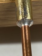
1/4 is the bigger tube and 1/8 if the smaller tube.Need to get it hot! You can use a torch but don’t get the solder in the flame. Heat gradually, remove torch and see if solder melts at the joint. If not, heat some more and repeat. Can’t remember the exact reaction (bubbling maybe) but it can get too hot. Work up to it gradually.
What is your bigger tube? 1/4” OD with 1/8” ID?
You can wrap some fine copper wire around the smaller tube and then slide that into the larger tube. That will hold the molten solder. As long as it still fits into the larger tube you are fine.
This won't win any beauty awards (still needs a bit of cleanup), but it is working!
Specific thanks to @Gina1 (of course) and @SGK for the Fusion360 design files for the shelf!
Edit: guess inlining the video won't actually work? Here's a link: video in action
Specific thanks to @Gina1 (of course) and @SGK for the Fusion360 design files for the shelf!
Edit: guess inlining the video won't actually work? Here's a link: video in action
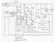
I am having a similar issue trying to find the schematic for this build. Does anyone know where I can locate the schematic for this build?Is there a schematic available anymore? Looks like the post on page 1 is missing it and the one on page 110 is so small it's impossible to read.
Thanks!
Some things that have changed since this was posted almost 5 years ago. The 110 VAC fans can be replaced by 12 VDC fans, The original trap door solenoid was discontinued by the vendor, not sure who makes a replacement. Some builders are using a solid state relay to control power to the inductor PCB..
Good luck with your build
Gina
Good luck with your build
Gina
I'm just getting started in building a full-function annealer with cartridge feeder and case drop, and I'd like to review the schematic posted much earlier in this thread to get a basic understanding of the system.
Unfortunately, the 'Rev-2 schematic' on page 110 appears to be corrupted or otherwise unreadable.
Has anyone archived a copy, or is a copy available somewhere else?
Any help is appreciated.
Scott
Yes, I realize that your initial annealer design has evolved with added features and alternate construction techniques, but having a look at the original schematic helps put things in perspective.
Thanks!!
Scott
Unfortunately, the 'Rev-2 schematic' on page 110 appears to be corrupted or otherwise unreadable.
Has anyone archived a copy, or is a copy available somewhere else?
Any help is appreciated.
Scott
Gina1 -
Yes, I realize that your initial annealer design has evolved with added features and alternate construction techniques, but having a look at the original schematic helps put things in perspective.
Thanks!!
Scott
The inexpensive Amazon SSR's are junk and most agree that they are not actually built to the specs advertised.Question for those with 48volt power supplies what SSR are you using? I have gone through 3 from Amazon they have all failed after 30-50 cases staying closed with the annealer not turning off. I’m drawing around 11 amps, last SSR was listed at 100 amps.
I have a 48V/1000W power supply, and I use a double pole mechanical relay so that I can use 12V to actuate the relay and switch both the positive and negative poles from the 48V power supply to the ZVS board.
URBEST 8 Pin JQX-12F 2Z DC 12V 30A DPDT General Purpose Power Relay for Remote Control, Automatic Control System: Amazon.com: Industrial & Scientific
URBEST 8 Pin JQX-12F 2Z DC 12V 30A DPDT General Purpose Power Relay for Remote Control, Automatic Control System: Amazon.com: Industrial & Scientific
www.amazon.com
A resister for what coil? The relay or inductor?Nothing like a good old fashioned relay.
Gina
PS just don't forget the varister for the coil.
Great idea. Are you using the socket those plug in?The inexpensive Amazon SSR's are junk and most agree that they are not actually built to the specs advertised.
I have a 48V/1000W power supply, and I use a double pole mechanical relay so that I can use 12V to actuate the relay and switch both the positive and negative poles from the 48V power supply to the ZVS board.
This is the one I've been using, and although it shows the switching to be limited to 250V AC / 28V DC, it is 30 Amps. So far, I have had no issues with 48V and about 15-20 Amps.URBEST 8 Pin JQX-12F 2Z DC 12V 30A DPDT General Purpose Power Relay for Remote Control, Automatic Control System: Amazon.com: Industrial & Scientific
URBEST 8 Pin JQX-12F 2Z DC 12V 30A DPDT General Purpose Power Relay for Remote Control, Automatic Control System: Amazon.com: Industrial & Scientificwww.amazon.com
Sorry, let me get my head out of the past. The original relay was a 110 volt AC and needed a varister across the relay coil to short out the CEMF voltage in the relay coil as the coil magnetic field collapsed when the relay was turned off from the timer. (protecting the timer).A resister for what coil? The relay or inductor?
With a 12 volt DC relay, all that would be needed would be a simple diode (like a 1N4002) wired across the relay coil (reverse polarity) to short out the CEMF from the relay coil when it is powered down from the timer.
CEMF = counter electro magnetic force ( voltage generated in the relay coil, opposite polarity.)
Not a good idea. The relay on the timer board is rated for 3 amps. The basic GinaErick pulls 8-12 amps to the induction PCB. Hence the need for the external relay.Just use the timer to drive the induction board directly
Similar threads
- Replies
- 74
- Views
- 47,299
- Replies
- 0
- Views
- 1,573
Upgrades & Donations
This Forum's expenses are primarily paid by member contributions. You can upgrade your Forum membership in seconds. Gold and Silver members get unlimited FREE classifieds for one year. Gold members can upload custom avatars.

Click Upgrade Membership Button ABOVE to get Gold or Silver Status.
You can also donate any amount, large or small, with the button below. Include your Forum Name in the PayPal Notes field.
To DONATE by CHECK, or make a recurring donation, CLICK HERE to learn how.

Click Upgrade Membership Button ABOVE to get Gold or Silver Status.
You can also donate any amount, large or small, with the button below. Include your Forum Name in the PayPal Notes field.
To DONATE by CHECK, or make a recurring donation, CLICK HERE to learn how.


