• This Forum is for adults 18 years of age or over. By continuing to use this Forum you are confirming that you are 18 or older. No content shall be viewed by any person under 18 in California.

Induction brass annealer redux

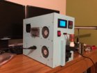
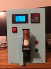
Just ran 50 308 cases one after the other at 50% duty cycle setting and no heat problem at all. Literally! Before the wire would be too hot to touch after a few cases. Now it's luke after 5 minutes and 50 cases. The ferrite heats up a little but in no way uncomfortable to touch. Before the heat would travel through the wire to the terminals on the ZVS board making the terminals hot. Now I don't feel any heat at the terminals.

Wow, nice. I'm able to run a little higher duty cycle with a water cooled arrangement, right now, but being able to ditch all the water stuff would be nice for a number of reasons. Will have to look back through the posts to see your coil design, too. A 50% duty cycle still isn't bad (I'm at about an 80% duty cycle currently).

Now looking forward to some conclusions on your "psuedo Aztec" mode stuff, too!
 
Here's a wiring diagramme for my build that I did for a mate in the UK who is implementing a copy of my build with my help. Maybe it is helpful. (The reason for all the colours is that I use a lot of multicolour ribbon cable and literally had to tell him which colour wire

May I have some grounding problems with this setup if it is used on a steel plate instead of on a wooden plate. The voltmeter is connected to port 30 and shows 0 when the relay connects, but the brass get hot.
 
My ongoing problem of dropping voltage (from 48V down to recently 27V under load) has been solved. I mentioned it here some time ago asking for suggestions as to the cause or solution, but no responses. Anyway, all has become clear. The power supply has failed completely. No fan, no green LED, no output voltage. I even changed the AC power lead to make sure it was not the problem. Over recent months I have checked every single connection on the entire project, tried a different annealer PCB, and eventually gave up. It was still working so don't worry about it. Only 5,000 case through it too, I was expecting more than that. Now I have to be patient and sit and wait for the new power supply to arrive.
 
Last edited:
My ongoing problem of dropping voltage (from 48V down to recently 27V) has been solved. I mentioned it here some time ago asking for suggestions as to the cause or solution, but no responses. Anyway, all has become clear. The power supply has failed completely. No fan, no green LED, no output voltage. I even changed the AC power lead to make sure it was not the problem. Over recent months I have checked every single connection on the entire project, tried a different annealer PCB, and eventually gave up. It was still working so don't worry about it. Only 5,000 case through it too, I was expecting more than that. Now I have to be patient and sit and wait for the new power supply to arrive.

Sorry your having problems.

Gina
 
My ongoing problem of dropping voltage (from 48V down to recently 27V under load) has been solved. I mentioned it here some time ago asking for suggestions as to the cause or solution, but no responses. Anyway, all has become clear. The power supply has failed completely. No fan, no green LED, no output voltage. I even changed the AC power lead to make sure it was not the problem. Over recent months I have checked every single connection on the entire project, tried a different annealer PCB, and eventually gave up. It was still working so don't worry about it. Only 5,000 case through it too, I was expecting more than that. Now I have to be patient and sit and wait for the new power supply to arrive.

Hi, I had similar problem. Board was drawing 8.5A with no brass and when entered the brass the voltage would drop dramatically. Even though the power supply was meant to be 600W it was providing much less. The power supply will never give more power (volts * amps) than its rating and drops volts accordingly. I put in a 1000w unit (overkill but was a good price) and no more problem.
 
I don’t have a need, I built a unit based on a Fluxeon board and designed a control board using a PIC to decode a 3 position thumb wheel switch for time (9.99 seconds max). It also controls turn-on of the annealer when a case is detected and opens the trap door. I did this 4 or 5 years ago (I think). It’s been posted somewhere on Accurate Shooter with pictures.

Does a fluxeon coil need a fluxeon board or can it operate with the standard induction board?
 
Hi, I had similar problem. Board was drawing 8.5A with no brass and when entered the brass the voltage would drop dramatically. Even though the power supply was meant to be 600W it was providing much less. The power supply will never give more power (volts * amps) than its rating and drops volts accordingly. I put in a 1000w unit (overkill but was a good price) and no more problem.

The new power supply I have ordered (due Wed this week) is 800W, so hope that is going to do the deal. The now dead one was 600W and was taking up to 8.7sec to anneal my 6.5CM Lapua cases. I think that is far too long and I was always concerned about the heat bleeding into the body of the case. My understanding, and my practice, of annealing times is that short and sharp is better that long and slow.
 
The new power supply I have ordered (due Wed this week) is 800W, so hope that is going to do the deal. The now dead one was 600W and was taking up to 8.7sec to anneal my 6.5CM Lapua cases. I think that is far too long and I was always concerned about the heat bleeding into the body of the case. My understanding, and my practice, of annealing times is that short and sharp is better that long and slow.
Yes, I was observing the same. The neck would eventually anneal but the long period was worrying due to potential changes introduced to the body. You certainly wouldnt want a case failure so good insurance to stay within normal parameters.
 
My new 48V 16.7A 800W power supply has arrived, and all I can say is WOW. During installation I decided to crank the voltage back to 40V after cooking a quite old and well used relay. The relay is $10 to replace and has done almost 6.000 cases so no tears about that. Where the old power supply was operating at 27V, with a drop from 48V, the new one is set at 40.5V and drops to 40.3V. Definitely confirms that the old unit was gradually dying.
The change from the sick power supply to this one is remarkable. I was taking 8.6sec to anneal my 6.5 Creedmoor Lapua brass, and that is now down to 3.4 sec, all confirmed with Tempilaq 750. The best time with the old 600W unit when it was new was 5.8sec, so the upgrade to 800W has made a significant difference, 2.4sec faster. 223 is down from 5.5sec to 2.2sec. I did manage to cook a few of those when I started by underestimating the power of this new power supply.
As stated above, I believe that short and sharp is better annealing than long and slow, so this is going to definitely meet that requirement. All I hope is that the other components in the 40V power system all survive the increase in power.
I want to anneal lots more cases now, but Covid restrictions have significantly reduced range time and therefore reduced empty cases.
 
Here is a brief history of the last 6 months as I moved from conception onto an operating PC case prototype and then a couple of models of the finalised arduino shield model that was developed by someone else as a share item in another forum here in NZ.
And now its done i am onto the flux model.
Initially I ran a 36 V system with the 1000V ZVS that used 8 capacitors in a series parallel arrangement. It turned out to be a slug so I got a newer ZVS like shown at the start of this thread.
I only recently came across this thread and joined the forum to post my version up. I had done a lot of research and reading though.

This first idea used a bare solid copper coil but it showed promise


This is the first water cooled coil with a pretty basic timer and everything very hands on and manual


Next came what was the finalised design and everything as I thought I wanted it.


Someone talked me into going with an all ACM chasis, that took a bit of working out and was a risk as I wasnt sure what the parasitic losses and problems might be.


In its final assembly it draws 4.8 A at idle and on Lapua .308 cases they anneal in 5.2 secs drawing 6.5 to 6.9 A it is oscilating at a frequency of 95Khz using 42V

The ferrite model I have gone back to a lower Voltage PSU as they really crank, this will take a bit more planning and I am banged up in a sling for a few months now recovering from RC surgery

 
Thanks to all for their efforts and generosity. I never would have thought this would be so easy. I've been lurking and absorbing information for weeks from this and a couple other forums/websites. Here is my incarnation of pretty much the original design, just packaged differently. Even though I have quite a bit of programming experience and am an Arduino/Pi fan, I decided to stay simple on this project. The trickiest part was fine tuning the coil. I chose to tune it to match the coil that came with the Induction PCB. It runs at 93khz with a 30-06 case loaded. Takes about 5.25 secs to get the 750 deg. tempilaq to turn just past the shoulder. No more torches and electric screwdrivers for me.
IMG_1178.jpg IMG_1179.JPG
 
Problems abound! I've been fighting one thing after another on this project and have ironed out most issues. However, there is one I can't seem to figure out. So I'm calling on the collective knowledge and experience for a possible solution.

The coils both factory and 1/8" diameter GinaErik specified coil heat up and draw almost 30Amps without any metal in the middle. No coils are touching. I've had 2 bad power supplies and 1 bad induction board during my build and this is the last issue to resolve.

All help and ideas are appreciated folks.
Thanks in advance
 
The coils both factory and 1/8" diameter GinaErik specified coil heat up and draw almost 30Amps without any metal in the middle. No coils are touching.
I had a problem on mine once when I didn't have a good connection between the induction board and the coil. The current shot up and the frequency went up to 121 khz. Luckily, I had a 15amp fuse between the 48V power supply and the induction board. The current was up to about 23 amps when the fuse blew. Now, I have little brass wings soldered to the coil at the connection points. It draws around 8 amps empty and about 12 amps with a 30-06 case in the coil. I've been setting the height where the neck of the case is in the middle of the coil's height.
IMG_1184.jpg
 
Last edited:
Problems abound! I've been fighting one thing after another on this project and have ironed out most issues. However, there is one I can't seem to figure out. So I'm calling on the collective knowledge and experience for a possible solution.

The coils both factory and 1/8" diameter GinaErik specified coil heat up and draw almost 30Amps without any metal in the middle. No coils are touching. I've had 2 bad power supplies and 1 bad induction board during my build and this is the last issue to resolve.

All help and ideas are appreciated folks.
Thanks in advance
It would be amazing bad luck to have all of those major items faulty. Perhaps you have not cabled things up 100% correctly and have accidentally shorted them out?

Are you using a metal case / cabinet for your annealer? If so make sure that you have plenty of clearance around the copper tubes of the coil throughout its entire length. It is also wise, with a metal case to have a rubber grommet around to cutout to insulate the case from the coil. If the coil is touching or even close to any metal it will spike the power. Let that continue for a second or two seconds and you will have damaged components.

Go back through your installation cabling in minute detail to make sure that you have done everything precisely in accordance with the different manufacturers requirements. Physically trace every piece of wire and check for shorts.

Disconnect all of the equipment, and then reconnect it one item at a time and energise. This will show which item is causing the problem when the power suddenly spikes after that new item is connected and energised.

Hope something in this helps.

Good luck.
 
If you have gotten this far good on you and dont give up. It could be something small like a loose terminal on the ZVS board causing things to heat up. Keep your wire runs as short as practicable, and use good quality cabling especially use heavy duty wiring on those parts that take a lot of current.
The original large diameter coil is no good for what we want to do, but is ok at a pinch for testing what is working.
Are you using a cooling system on your coil?
How are you powering the 12V DC side of things ( like timers and relays ) How are you powering your ZVS board and at what V's
 
Last edited:
NC Tinkerer

My build is so old I can’t remember the details but I think Fluxeon told me how many turns the coil should be. The GinaErik design may dictate something else but they really only needs to envelop the neck, shoulder and a little of the body. I also made the ID as small as practical for better coupling. I made different coils for different cases. A friend made these mandrels for me. I was concerned about the possibility of flattening of the tubing. The odd looking one on top is for the other bends.
upload_2020-8-18_12-10-50.jpeg
 

Upgrades & Donations

This Forum's expenses are primarily paid by member contributions. You can upgrade your Forum membership in seconds. Gold and Silver members get unlimited FREE classifieds for one year. Gold members can upload custom avatars.


Click Upgrade Membership Button ABOVE to get Gold or Silver Status.

You can also donate any amount, large or small, with the button below. Include your Forum Name in the PayPal Notes field.


To DONATE by CHECK, or make a recurring donation, CLICK HERE to learn how.

Forum statistics

Threads
165,261
Messages
2,192,335
Members
78,785
Latest member
Vyrinn
Back
Top