• This Forum is for adults 18 years of age or over. By continuing to use this Forum you are confirming that you are 18 or older. No content shall be viewed by any person under 18 in California.

Induction brass annealer redux

One page "1" of this tread, the part I called out for the power relay is a DPST ""contractor" relay. It connects/disconnects both the + and - power leads at the same time. The one I used has a 110 volt AC coil. If you wish it can be ordered with a 12 volt DC coil. Using a "car" relay, IMHO is unwise in that it was not designed for the higher contact voltages and the contacts are too close for that voltage. With a contractor relay there is greater distance between the contacts. In the 2 + years since I have built my annealer, I have put 1,000's of cases through it and have never had a problem with the contractor relay. Last year one of the builders was having a problem with arcing in the "car" relay he was using. I opened my unit and took the cover off the contractor relay to check for arcing. There was no sign of any arcing.
Some builders have used Solid State Relays. I do not have a part number for that. Somewhere in this thread there is a schematic for that change.
Just remember to add the correct diode/varistor across the coil of the relay.
Hope this helps

Gina

PS I like the click/clack that the relay makes during each annealing cycle...:rolleyes:


Ok, thanks I thought so, and it looked so, but before doing a lot of wiring I just wanted to ask. I like the click/clack too. Those SSR guys/gals won't get to hear that. :-(
 
Anyone else have the problem with the necks heating up too fast and glowing slightly before enough heat gets to the shoulder? Or is it really an issue? To me it seems quiet common from I’ve seen from others.
 
I noticed this. I observed the mouth of the case turning to glow in a darkened room and this glow shooting down the neck just before ejection. I was also having a little difficulty getting the annealing brass colour change to extend much below the shoulder. I decided to place the bottom of the shoulder at the centre of the work coil (rather than the top). This is where the induction forces are greatest. Obviously the thinnest part of the brass 'heats to glow' first but if you place the thickest part of interest at the most intense part of the induction field there's a bit more balance to the process. But then we are all guessing as to what's really happening and what's 'correct'.
 
I noticed this. I observed the mouth of the case turning to glow in a darkened room and this glow shooting down the neck just before ejection. I was also having a little difficulty getting the annealing brass colour change to extend much below the shoulder. I decided to place the bottom of the shoulder at the centre of the work coil (rather than the top). This is where the induction forces are greatest. Obviously the thinnest part of the brass 'heats to glow' first but if you place the thickest part of interest at the most intense part of the induction field there's a bit more balance to the process. But then we are all guessing as to what's really happening and what's 'correct'.

ditto...

i'm doing 6BR brass, running about 575 watts of power, with an anneal time of 5.4 seconds. Tempilaq paint (700F) shows 1/4 inch below the shoulder is annealed. Shoulder is 5/8 into the coil. In a dark room, with these settings I do not see a glow. which is good as I'm not over heating my brass at the neck. So from the neck down to 1/4" below the shoulders is "annealed"
 
Last edited:
I noticed this. I observed the mouth of the case turning to glow in a darkened room and this glow shooting down the neck just before ejection. I was also having a little difficulty getting the annealing brass colour change to extend much below the shoulder. I decided to place the bottom of the shoulder at the centre of the work coil (rather than the top). This is where the induction forces are greatest. Obviously the thinnest part of the brass 'heats to glow' first but if you place the thickest part of interest at the most intense part of the induction field there's a bit more balance to the process. But then we are all guessing as to what's really happening and what's 'correct'.
Sounds good. Posted a video of my induction machine on “Reloading central” and a few folks kept complaining about the faint glow. My .270 win brass is annealing at 4.9 seconds and my 300 win is annealing at 3 seconds. Assuming it’s due to the longer neck on .270 win.
 
Reloading 22-250 brass for a friend, I kept getting split necks annealing to 750° tempilaq temps. No glow could be seen. Bumped up the annealing time to the point I saw a decent red glow and the splitting stopped.
 
Has anyone had problems with the start and stop switch? I can get the start switch to work, but as soon as I wire in the stop switch they both light up and neither circuit will work with them.
 
Last edited:
Has anyone had problems with the start and stop switch? I can get the start switch to work, but as soon as I wire in the stop switch they both light up and neither circuit will work with them.

The start/stop circuit of the timer is very simple. I'm not sure of what your trying to do, with lighting them up. Try this.. disconnect what ever circuit, your using to try to get the switches to light up. Make it just a straight switch circuit as shown on page 1 schematic of this thread.
If that works send me a schematic of what you were trying to do.. OK

Gina
 
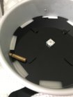
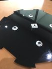
FYI I encountered an unforeseen issue with my feeder discs or, more specifically, the bumpers on them. If a case (particularly one at the bottom of the pile) aligned itself just so the bumper could push the head of the case such that the mouth wedged itself on the edge of the hopper. While hard to replicate by hand this pic gives you the idea:

IMG_3485.JPG

It was particularly an issue with the shorter cases. So I finally found these https://www.amazon.com/gp/product/B07882C9KC/?tag=accuratescom-20 which I think will do a better job. While there is still a small vertical lip I think a case head will ride over the bumper if wedged as above.

IMG_3583.JPG

BTW I now order any of my 3D printed (Multi Jet Fusion process) parts directly from the service provider rather than from 3dHubs.com. @BillK55 asked me to tweak some of the dimensions of my printed shelf for him. The shelf, paddle for trap door and two case-size dependent inserts only cost about $22. Printing the parts for the autofeeder are, in my opinion, cheap.
 
These momentary switches light up when pressed/used or can be wired to stay on.

https://www.amazon.com/dp/B01I9KDVWQ/?tag=accuratescom-20

KIS... Keep it simple. If you used just the NO contacts of your switches to operate the timer ... no problem. Trying to tie power into the switch to operate the LED, in conjunction with the switch
screws up the timer. Nice idea to light the switch when you push it... but in this case, it was not designed for it.
Sorry.
If you tie the LED, by it's self, to a power supply (the 12VDC) you could have the LED lit all the time, without effecting the timer.
 
Last edited:
KIS... Keep it simple. If you used just the NO contacts of your switches to operate the timer ... no problem. Trying to tie power into the switch to operate the LED, in conjunction with the switch
screws up the timer. Nice idea to light the switch when you push it... but in this case, it was not designed for it.
Sorry.
If you tie the LED, by it's self, to a power supply (the 12VDC) you could have the LED lit all the time, without effecting the timer.
Haven’t even been using the No Contact since the instructions say not to.
 
What instructions ? NO = normally open contacts on the start / stop switches You have 5 terminals on your switches. For the switch part NO, NC and common. Your start /stop wires from the timer .( terminals 1,2 & 12) go to these terminals. (NO and common.) To light your LED ring (always on) connect the LED terminals to the +12VDV PS.
 
A momentary switch merely makes a momentary connection. I don't see why, in principle, the momentary connection couldn't connect two wire runs. One, grounding Pin 2 of the Sestos timer (by momentarily connecting pins 2 and 1) and, two, connecting the LED to its supply (or ground return). I'm not sure what you gain from a momentary lighting of the switch LED ring but if that's what you want it should be possible.

I still don't think we have clear communication as to what you are trying to do and how you have attempted to wire things. I don't think the problem is your selected switch.
 

Upgrades & Donations

This Forum's expenses are primarily paid by member contributions. You can upgrade your Forum membership in seconds. Gold and Silver members get unlimited FREE classifieds for one year. Gold members can upload custom avatars.


Click Upgrade Membership Button ABOVE to get Gold or Silver Status.

You can also donate any amount, large or small, with the button below. Include your Forum Name in the PayPal Notes field.


To DONATE by CHECK, or make a recurring donation, CLICK HERE to learn how.

Forum statistics

Threads
165,798
Messages
2,203,672
Members
79,130
Latest member
Jsawyer09
Back
Top