• This Forum is for adults 18 years of age or over. By continuing to use this Forum you are confirming that you are 18 or older. No content shall be viewed by any person under 18 in California.

Induction brass annealer redux

Hello, sir.
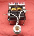
May I ask what is inserted into a coil? How many turns in it?
Thank you.

That's a small 3/4 inch PVC pipe insert to keep my 6.5 creedmoor brass centered. My coil is 8 turns but a little smaller at .9 inch ID roughly on this annealer. My new annealer is 1 1/8 inch ID coil and will still use 3/4 inch PVC but with a coupler which is 1.1 inch OD makes for a nice fit and keeps brass centered. Also I'm using the heat resistant fiber sleeve that takes up some space and keeps the coils from touching one another.
 

Attachments

  • small-insert.jpg
    small-insert.jpg
    48.9 KB · Views: 195
  • annealer2-1.jpg
    annealer2-1.jpg
    200.9 KB · Views: 215
  • annealer2-insert.jpg
    annealer2-insert.jpg
    102.1 KB · Views: 176
I upgraded my induction board to an 1800 watt/40 amp version that is much higher quality. Huge heat sinks on the mosfets and dual fans above the caps.
It seems more efficient requiring 2.8 sec for my 284 brass vs 3.2 at slightly lower amps. Does not overheat feeding brass quickly. Did 200 cases as fast as I could with a few short breaks to measure temps.

https://www.amazon.com/dp/B0794XXQ7S/?tag=accuratescom-20
7074AC2B-FE0F-4F37-9AA8-11658BE68D3A.jpeg
E413DE81-EC2F-4CA0-96D1-8C62136C0C86.jpeg
D125FAA6-B80D-45CC-AC98-A3BBEC334071.jpeg
 
Last edited:
WOW !!!
With fans also !

Just when you thought it was safe to build, now you need a larger/hi current PS....sheesh.

good find.

Gina
 
I upgraded my induction board to an 1800 watt/40 amp version that is much higher quality. Huge heat sinks on the mosfets and dual fans above the caps.
It seems more efficient requiring 2.8 sec for my 284 brass vs 3.2 at slightly lower amps. Does not overheat feeding brass quickly. Did 200 cases as fast as I could with a few short breaks to measure temps..

Oh good you found and tried it, outstanding.
I’m still getting parts for mine. I’m very close to having everything for a basic model to start with then add the other stuff later
 
I upgraded my induction board to an 1800 watt/40 amp version that is much higher quality. Huge heat sinks on the mosfets and dual fans above the caps.
It seems more efficient requiring 2.8 sec for my 284 brass vs 3.2 at slightly lower amps. Does not overheat feeding brass quickly. Did 200 cases as fast as I could with a few short breaks to measure temps.

What voltage / current does this board require to get the anneal times down? Thanks
 
It takes 780 watts with this board to anneal my 284’s in 2.7 sec. I’m using a 1k watt/36 v power supply and smaller diameter coil.
 
Last edited:
Hi Bob...

The original coil size (1 1/8") was designed for .308 cases. That said, it will work equally well for any case in that diameter size. With smaller cases ie: .223, the case wall is further away from the coil, so less energy is transferred to the case and it takes longer to heat up the case to annealing temperature.

The one thing you have to be mindful of with a work coil and drop hole that is sized for larger cases is centering smaller cases properly. Even centering 308 cases in my shelf hole of 15.5mm proved an issue. I had the coil slightly off-centre from the hole - about 1-2mm off. A 308 case settled at the front edge of the drop hole exactly where it would exacerbate the slightly off-centre work coil. (That is closer to the coil on one side versus the other.) Even though we are talking only a couple of millimetres for each they added. The case annealed markedly further on one side versus the other. So I have now designed inserts for both 308 (or any circa 12mm case) and 223.
 

Attachments

  • IMG_3542.jpg
    IMG_3542.jpg
    496.8 KB · Views: 117
FYI here's a pic of the inside of my build which was taken prior to loading the coolant. (Click on the thumbnail and then show in original and you get a higher res image.)

IMG_3538.jpg

You can see the 4 temp measuring NTC. Of the two which 'drive' the radiator fan one is fixed to the radiator itself while the other is attached to the 1/4" copper pipe which carries coolant into the work coil. Of the two which drive the other fan, one is placed near the induction board caps towards the front of the enclosure (there's no point haven't it too close to the caps - we know they produce heat, we just need to ensure the general ambient temp is staying under control) while the other is on the other side of the induction board elevated to measure temp towards the top of the enclosure.

I wrapped the 1/4" copper tubing that passes over the caps in Kapton tape.

My control board just attaches to the sidewall of the enclosure.
 
Everything's mounted in the box but nothing is wired up yet. Using Old School Analog Voltage and Amp gauges. 50V and 20A should be ok I think. Next a little wiring each day and soon it may be annealing brass. On the prototype I had the same trouble others had with the main relay. Contacts burning or welding together after about 20 - 40 anneals. Went from 40 amp auto to 80 and it happened all over again. I had one more 40 amp auto relay like the first one and said what the heck and put the capacitor across the contacts. It's been a couple hundred anneals now and no problem. The new in the box system will use a new much larger relay with cap across the contacts.
 

Attachments

  • newAnnealerInBox1.jpg
    newAnnealerInBox1.jpg
    167.4 KB · Views: 330
  • newAnnealerInBox2.jpg
    newAnnealerInBox2.jpg
    218.4 KB · Views: 344
  • annealer-relays.jpg
    annealer-relays.jpg
    81.9 KB · Views: 302
One more photo of the little auto relay with capacitor. It's a 100ufd 150v electrolytic type. It may not be necessary with a large relay but it can't hurt.
 

Attachments

  • annealer-1RelayCap.jpg
    annealer-1RelayCap.jpg
    57.2 KB · Views: 129
Contacts burning or welding together

I think I see you have a DPDT relay. Way back in the thread someone had recommended temporarily removing the cover from the relay and then taking the normally closed contacts (the ones you're NOT using), and bending them back some (away from the moving center contact), so that you get more effective gap when the coil de-energizes and the normally open contacts open up.

The capacitor you added is across the contacts? I must be missing something, because I'd have thought that would have made your arcing issue worse.
 
I've finally have been able to work on the annealer again after getting back from the sand box. Just having problems with the stop momentary switch. Don't know why, but its wired correctly to 1 and 12, but doesn't work when I press it, but will light up when I press the start momentary switch.
 
I think I see you have a DPDT relay. Way back in the thread someone had recommended temporarily removing the cover from the relay and then taking the normally closed contacts (the ones you're NOT using), and bending them back some (away from the moving center contact), so that you get more effective gap when the coil de-energizes and the normally open contacts open up.

The capacitor you added is across the contacts? I must be missing something, because I'd have thought that would have made your arcing issue worse.

Well the auto relay is only spdt at least the one I've used and still use on the breadboard version. My new HD DPDT relay I'll use both sets of contacts. With the capacitor + to the power supply side and - to the annealer board direction just like the prototype. The 100ufd / 150v was just something I had in my junk box of parts and it seems to work well so far. The only concern I have is when the relay energizes putting power back to the board will the cap arc the contacts some or none. Anyone know? Maybe but a resistor across the cap to discharge it a little during the solenoid drop brass cycle. Maybe just over thinking it.
 
Last edited:
Also, what have y'all been dipping y'alls coils in to protect them? Don't really feel like unsoldering my coil to put a sleeve on it. :/
 
Ok I would like to ask Gina or Eric a question about the power relay. I took a quick look back in the threads but still not 100% sure, so are you guys breaking power to both the Positive and the Negative of the Annealer circuit board? Using the DPDT relay for both sides? I haven't wired my box yet so nows the time to ask dumb questions. Maybe I don't need that capacitor if that's the case, thanks BillK55 for heads up. Anyone here been to 486L school?
 

Upgrades & Donations

This Forum's expenses are primarily paid by member contributions. You can upgrade your Forum membership in seconds. Gold and Silver members get unlimited FREE classifieds for one year. Gold members can upload custom avatars.


Click Upgrade Membership Button ABOVE to get Gold or Silver Status.

You can also donate any amount, large or small, with the button below. Include your Forum Name in the PayPal Notes field.


To DONATE by CHECK, or make a recurring donation, CLICK HERE to learn how.

Forum statistics

Threads
165,324
Messages
2,193,173
Members
78,819
Latest member
DJT
Back
Top