• This Forum is for adults 18 years of age or over. By continuing to use this Forum you are confirming that you are 18 or older. No content shall be viewed by any person under 18 in California.

Induction brass annealer redux

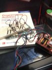
I had a similar problem that took me ages to fix. I eventually found a loose connection on the shunt for the volt/amp meter. This was after confirming all of the work I did first including each and every solder joint, tightening each screw, etc. I assumed that my work was most probably the one to be faulty rather than the purchased equipment. I was correct. I also recommend separating your 12V and 48+V wires as you can get some problems from bunching significantly different voltages together.

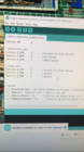
I now do an empty power level test before each annealing session to ensure it is constantly in the same area and I record that each time. There is a photo of my volt/amp meter on the previous page -78. My annealer runs 48V at 10.7A and 420 watts with an empty coil. That increases when a cases is dropped, but each caliber and each brand of brass within each caliber is different metal composition, so the times to anneal are also different. My 6.5 Creedmoor Lapua brass takes 7.8secs, 223 Remington brass 4.1s, 223 Lapua brass 4.8s, 22-250 Hornady brass 5.4. I do the first four cases and last two cases of each session with Tempilaq 750 and they are all good at those times.

Hope you find your problem.
 
Are most people building off the original details at the start of this thread? I've read through several of the postings and see a lot of references to capacitors and such around certain components to help SSR and such. More recently, reducing the frequency of the power supply? Or, do I just need to read every page :)
 
Finished the table height adjust with the stepper motors and Arduino! I’ll post the code later, but I used and Nema 17 stepper, Arduino Uno, CNC Shield and A4988 controllers. The steppers go up and do via momentary push buttons. I used the CNC shield because it allowed me to easily use the 2 steppers and clone an axis. Which meant easier programming. I’ll also post a video later. I have many hobbies so this has taken longer than I wanted, but the main work is done. I just have to install it on the annealer when I get back from being overseas!
 

Attachments

  • C8DFDDB7-158D-4292-BC88-A1AC7D89FBD1.png
    C8DFDDB7-158D-4292-BC88-A1AC7D89FBD1.png
    3.5 MB · Views: 248
  • 5F4C6896-F529-4AE2-982E-2B250FA02D72.jpeg
    5F4C6896-F529-4AE2-982E-2B250FA02D72.jpeg
    208 KB · Views: 272
  • 48E3F96F-AC62-494E-80D4-7614471646EB.jpeg
    48E3F96F-AC62-494E-80D4-7614471646EB.jpeg
    584.4 KB · Views: 259
Hi Gina,

need a little help and advice if you can!

I have managed to complete the project, but I have a few anomolies that are getting the better of my limited electrical knowledge. On first start up, i set the voltage, which was around 43 volts and gave me 8.1amps in an unloaded coil, once i dropped a case, the amps went up to around 11.5amps and an anneal time of 10.45s, this was for a.308 case. I did play with the height settings and ensured that the case was as central as possible. With Tempilaq 750, it annealed to around 4mm below the shoulder, so it appeared that all was well. 60 cases later, (after an overnight rest) i fired the unit up again for a second test, but this time it showed the unloaded coil as drawing around 2.5amps, and a loaded coil as just managing to hit 6.8amps with a stupid annealing time. In order to get the power up, I have had to increase the voltage to 53.5volts, this now anneales in 7.5 seconds and amps hitting 11.5 amps. I am thinking that the ZVS unit is defective, but I have no idea in reality, any ideas or thoughts?

Two things come to mind. Check for a short in the annealing coil (two winding's touching) Or your ZVS PCB has gone bad. (it has happened to other builders).
Unfortunately, electronics is like that. A board, power supply, an assembly, is built and given a quick test, and then shipped. No burn in periods are done. Rule of thumb is if it lasts the first 100 hours it will last the life of the unit.

hope this helps

Gina
 
Stepper motor code: Arduino Uno, CNC Shield, nema 17 steppers and push buttons.

Code:
#define EN        8

//Direction pin
#define X_DIR     5       //cloned for both motors
#define Y_DIR     6       //up button
#define Z_DIR     7       //down button

//Step pin
#define X_STP     2       //cloned for both motors
#define Y_STP     3       //unused
#define Z_STP     4       //unused


//A4988
int delayTime=240; //uS Delay between each pause - effective speed control
int stps=1;// Steps to move - 3200 is one rev
int UPbuttonState = 0;      //initial up button state to 0
int DOWNbuttonState = 0;      //initial up button state to 0


void step(boolean dir, byte dirPin, byte stepperPin, int steps)
{

  digitalWrite(dirPin, dir);

  for (int i=0; i < steps; i++) {
    digitalWrite(stepperPin, HIGH);
    delayMicroseconds(delayTime);
    digitalWrite(stepperPin, LOW);
    delayMicroseconds(delayTime);
    }

}

void setup(){

  pinMode(X_DIR, OUTPUT); pinMode(X_STP, OUTPUT);
  pinMode(Z_DIR, INPUT); pinMode(Y_DIR, INPUT);
  pinMode(EN, OUTPUT);
  digitalWrite(EN, LOW);
}

void loop(){

// read the state of the pushbutton value:
  UPbuttonState = digitalRead(Y_DIR);

  // check if the pushbutton is pressed.
  // if it is, the buttonState is HIGH:
  if (UPbuttonState == HIGH) {
    //move motors up:
    step(true, X_DIR, X_STP, stps);
  }
  if (UPbuttonState == LOW) {
    //do nothing:
    //step(true, X_DIR, X_STP, stps);
  }

  // read the state of the pushbutton value:
  DOWNbuttonState = digitalRead(Z_DIR);

  // check if the pushbutton is pressed.
  // if it is, the buttonState is HIGH:
  if (DOWNbuttonState == HIGH) {
    //move motors down:
    step(false, X_DIR, X_STP, stps);
  }
  if (DOWNbuttonState == LOW) {
    //do nothing:
    //step(false, X_DIR, X_STP, stps);
  }
}
 
Well I'm feeling more excited about by basic build each day. I have had more that half the parts arrive, and major parts to come are volt/amp meter, large power supply, shunt, and some other little stuff. Trying to wait on all the parts before I get building.
2 questions, just to confirm. The fuses used in the original are 3 amp (I think the diagram had 1 amp, but they were changed)? And the internal diameter of the induction coil is 1 1/8", with 8 coils ? And the coil is made of 1/8" copper tube? I have the copper tube, and some ali tube that measures a few thousandths under 1 1/8", to use as a mandrel.
cheers
Brendon
 
Are most people building off the original details at the start of this thread? I've read through several of the postings and see a lot of references to capacitors and such around certain components to help SSR and such. More recently, reducing the frequency of the power supply? Or, do I just need to read every page :)

Keep it simple don't modify the original plans or board. Your asking for trouble if your not into electronics. The power supply is DC no frequency to be concerned with. Like 36 or 48 volts DC 15 or 20 Amp should be plenty, and SSR , well everyone knows what I think of them. Relays are much simpler, don't have to be babied and just work if you use a large rated one for amps DPDT. The white insulative / heat resistance sleve for the induction coil is a good idea for preventing shorts and it looks good. Good Luck Fliers.... HB
 
Well I'm feeling more excited about by basic build each day. I have had more that half the parts arrive, and major parts to come are volt/amp meter, large power supply, shunt, and some other little stuff. Trying to wait on all the parts before I get building.
2 questions, just to confirm. The fuses used in the original are 3 amp (I think the diagram had 1 amp, but they were changed)? And the internal diameter of the induction coil is 1 1/8", with 8 coils ? And the coil is made of 1/8" copper tube? I have the copper tube, and some ali tube that measures a few thousandths under 1 1/8", to use as a mandrel.
cheers
Brendon
Any small changes (coil size), by a few thousands will not make and great difference. 3 amps will do just fine. As hambone says KIS (keep it simple) Slip on coil covering is a great idea.
PS. I like relays also
Gina
 
Like the previous folks have said, unless you have an understanding of electronics and so on stick to the basic plan or deviate very little from them. Example using a different push button or solenoid. Though the on button for mine requires a relay because it cannot handle the power that would of went through it. So even small changes can have consequences. Those of us who have done some “over the top” things know electronics or just enjoy learning. Such as myself.
 
Last edited:
Any small changes (coil size), by a few thousands will not make and great difference. 3 amps will do just fine. As hambone says KIS (keep it simple) Slip on coil covering is a great idea.
PS. I like relays also
Gina
Relay instead of the Packard C320?
 
Hi guys, I found this tread and was so excited! I learned a ton after reading 79 pages. Before that I purchased ZVS 1000W board and 500 watt adjustable voltage 0-51.7v and found that it took way too long to heat up piece of 223 brass so I gave up on that idea but it did wonders for tempering my O-1 steel hollow punches that I machine until my board stopped working on 5th try. Reading the forum first I realized that the key was custom coil and I learned that cooling is essential, I knew in the back of my mind that board was getting insanely overheated, the coils had burned and even ordered small water pump and protective sleeve off ebay but put it off installing due to fear of water leaking and frying board. I have water cooled my PC over 10 years so this area I am familiar and have spare radiator. I will try to repair the board if it's cost reasonable thanks to earlier link posted about guy who repaired them. Also right off the bat I was thinking about SSR since I am familiar with it from making PID controller for lead pot and using Arduino to control it and this is how I made my $20 annealer using torch and stepper motor controlled by Arduino. It was single fed but worked, but I like flameless design! I am kind of surprised that SSR failed for Bruce, the one I am using for PID is running 700 watt pot for hours at the time and it's switching it on and off fast to maintain programmed temperature and has worked flawlessly for couple years, it cost me like 4-5 bucks from eBay, I went ahead and ordered the nicer 4 channel relay that Bruce used because someone posted here for $22 - again thanks to all the great people that shared the info. Really like David's core flux concentrator with it's lower current draw I could buy a smaller cheaper 36v power supply, only thing I am concerned about is doing mass annealing session. I was thinking of going with slightly larger tubing for better flow and adding copper / aluminum blocks to mosfets with copper tubing passing through since the copper tube is passing them I can put them in the same water loop, maybe adding custom water block glued to the PCB bottom. What do you guys think?
 
Dima-

Nothing wrong with gluing on some water blocks and using the coil coolant system for the board(s). I was going to do the same thing at one point.
 
Found this copper tubing pretty cheap. It's only 3 ft (1m) but I think that's enough, did anybody measure how many inches you need for original GinaErick spec? They also have different sizes I want to try like 4mm. 3.5mm is as closest to 1/8" Oh and one more thing it's only 0.019" wall thickness so more space for water flow! https://www.ebay.com/i/173570921477?rt=nc&_trkparms=aid=222007&algo=SIM.MBE&ao=2&asc=20160908110712&meid=38c369f67a1a4587b1baa6c2945d2e8c&pid=100677&rk=2&rkt=24&sd=173570921024&itm=173570921477
 
Last edited:
3mm is closer to 1/8. Pay attention to the wall thickness of the tubing, very small ID (1.0mm) requires a pump with some oof-dah. You will need over 1 meter to make a coil with a long inlet/outlet run. Try to find 0.5mm wall or thinner 3mm OD 101 (pure) copper. 3.5mm will work too.


8 x 28mm x 3.1416 = ~700mm just for the coil windings.
 

Upgrades & Donations

This Forum's expenses are primarily paid by member contributions. You can upgrade your Forum membership in seconds. Gold and Silver members get unlimited FREE classifieds for one year. Gold members can upload custom avatars.


Click Upgrade Membership Button ABOVE to get Gold or Silver Status.

You can also donate any amount, large or small, with the button below. Include your Forum Name in the PayPal Notes field.


To DONATE by CHECK, or make a recurring donation, CLICK HERE to learn how.

Forum statistics

Threads
165,859
Messages
2,204,403
Members
79,157
Latest member
Bud1029
Back
Top