• This Forum is for adults 18 years of age or over. By continuing to use this Forum you are confirming that you are 18 or older. No content shall be viewed by any person under 18 in California.

Induction brass annealer redux

Gina do you take the primers out before you anneal? Perhaps I dont need to ask that question I remember seeing a post with a broken glass tube when a live primer went off.
Reason I ask is that AMP say to remove primers. I cant see it making a big difference to the anneal process or any extra current being drawn any thoughts?

No, I leave the "spent" primers in (lesson learned). I do not think it makes any difference, since the annealing is taking place at the neck and shoulder. after annealing I do the de-capping and re-sizing.
 
Board is not oscillating or starting up correctly. Simply bypass the SSR and wire directly to the board with one wire like - minus side and touch the + positive side wire to other power input for 3 - 5 seconds. Be sure to have brass in the coil. It (brass) should get hot hot hot. If that doesn't work board has to be bad if it's getting 30 to 40 volts dc ok. If that direct power method works wire in only one SSR and try it. HB

I have just tried this and the brass is indeed getting hot. It seems I was a muppet and got my wires crossed as to live and neutral yesterday when I connected the induction board. Both SSRs are now cooked and stuck on, whether it was from this or another reason, I don't know. However the induction board seems to be working. Do I need any protection for the SSR (once I get a replacement) from the induction board?
 
I bought the Temilaq pens quite some time ago when I started playing with annealing. I quickly found that they did not work as needed for brass cases esp in flame setups.
Anyway a tip for anyone that fell into the same trap as me. I found that you can grind up the pen material and mix it with a little bit of metho and it makes a liquid / past as the mentholated spirits dries and works as well if not better than the liquid Tempilaq. It also seems to re dissolve although that is not correct as it doesn't dissolve but goes back into suspension pretty well again without needing to grind it up to much again.
 
I have just tried this and the brass is indeed getting hot. It seems I was a muppet and got my wires crossed as to live and neutral yesterday when I connected the induction board. Both SSRs are now cooked and stuck on, whether it was from this or another reason, I don't know. However the induction board seems to be working. Do I need any protection for the SSR (once I get a replacement) from the induction board?
 
Hi Everyone, I have nearly completed my own build of the GinaErik induction annealer. I have gone for more or less the original design but have run into an issue today when trying to run it the first time.
Today I finally received the correct induction board from china (took 3 attempts). On opening the package, I noticed that one of the coils on the board had one leg that was not soldered into the board, so I fixed that (I think) and got it all mounted, connected to the heater coil and wired it in. I started it up to have a go and was getting no heat into the brass at all. My relays are working and running the "Annealing" LED and the heatsinks on the induction board are getting hot. Both SSR relays are also getting quite hot, but no heat into the brass.
I did wind the heating coil backwards by accident and since I dont have enough tube to make another just yet I thought I would try it anyway. Is it important for the coil to be wound clockwise/anti-clockwise? will this be what is causing my issue or is it likely a faulty induction board?
The only other major difference I have to the original design is that I am using 2 SSR relays instead of the contact relay as I am not able to get the correct relay in New Zealand for a reasonable price. I have one relay on each leg of the induction board. Is this necessary? Could this be causing the board to not start fast enough or something like that?

This project is about the limit of my electrical capability and I am really just following the instructions provided (thanks Gina) without having a proper understanding of what is going on.

Thank you everyone on this thread for all the information and especially to Gina for starting it all.

Also very nice job on your annealer SixtyTen, you do good work....I think you'll be annealing brass like crazy soon... HB
 
View attachment 1085448

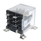
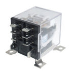
Like Gina says "keep it simple" and for under $8.00 Large Heavy Duty 12vdc coil DPDT no more problems

https://www.ebay.com/itm/JQX-12F-2Z...h=item2a5cab6291:g:SNAAAOSwys5WV1o4:rk:9:pf:0

Here's a link to a bunch of them to look a.......

https://www.ebay.com/sch/i.html?_fr...-12F+2Z+DC+12V++DPDT+General+Purpose&_sacat=0

Have you used these yet? Not all 'heavy duty' relays are created equal.
If the contacts can't handle 24v+ and 20A, they will weld and stick together in only a few cycles, you'll have to do an emergency shutdown somehow.
 
Have you used these yet? Not all 'heavy duty' relays are created equal.
If the contacts can't handle 24v+ and 20A, they will weld and stick together in only a few cycles, you'll have to do an emergency shutdown somehow.
AnnealerRelay.jpg
This is the one I've found that works. The little black ones that say heavy duty 30 or even 40 amp I've welded the contacts together on a couple. On those black ones they were SPST and I used them on one side of the power like the + side. Didn't work very long. Well they worked longer with a cap across the contacts I guess.
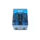
This big one is very very heavy duty and it is DPDT and I use it to switch both sides like Gina suggests.
Not using a capacitor across the contacts either. I think it has to do with distance in the relay from one set of contacts to + pos and one set of contacts to - neg and simply a larger gap. It has not been a problem I've had hundreds of brass in the coil and trap door now. I'm thinking this relay is a winner if used on both sides of the power input to annealer. I also have two power switches to shut down the annealer in a emergency ...HB
 
I have just tried this and the brass is indeed getting hot. It seems I was a muppet and got my wires crossed as to live and neutral yesterday when I connected the induction board. Both SSRs are now cooked and stuck on, whether it was from this or another reason, I don't know. However the induction board seems to be working. Do I need any protection for the SSR (once I get a replacement) from the induction board?

I had the same SSR as you show in your photos, and it also cooked - after only 38 cases. I have now gone to this one (link below), and have successfully, and without incident, annealed 3,500 cases. The relay doesn't even get hot. It is a 250V 30A relay. I am in Australia but I am sure they will mail it to you or you would find something similar wherever you are. There two terminals for the control current and the other two for positive from the power supply to the induction heater. I have a kill switch fitted between power supply and the relay.

You now have two replacement options, Hambone1971's and mine. And they both work.

https://www.jaycar.com.au/heavy-duty-chassis-mount-relays-30a/p/SY4040

SY4040-heavy-duty-chassis-mount-relays-30aImageMain-515.jpg
 
Last edited:
I have just tried this and the brass is indeed getting hot. It seems I was a muppet and got my wires crossed as to live and neutral yesterday when I connected the induction board. Both SSRs are now cooked and stuck on, whether it was from this or another reason, I don't know. However the induction board seems to be working. Do I need any protection for the SSR (once I get a replacement) from the induction board?

Do I need any protection for the SSR (once I get a replacement) from the induction board?

annealerboardfuse.jpg
A simple 15 amp fuse in line from your power supply would save the day when things are/go wrong. HB
 
I am going to put a diode the fast response type FR607 from the + terminal ie the induction board side of the + 48V to the negative rail of the 48 V power supply (not across the terminals of the SSR). Perhaps a better point to take the it may be back to a real Ground point.

Not sure the fuse would work for this particular issue. It would protect the induction board and the PS although that already has short circuit protection. It would protect the SSR against more stable and longer occurring over current faults. They are most likely letting out the smoke due to too high a voltage and of reverse polarity.
 
Last edited:
Obviously the short circuit protection did not work, when things go bad wrong you can't beat a .25 fuse. It alerts you to a problem before the smoke and big dollar headahes start. I would even use a smaller 10 amp fuse untill I was sure of my wiring. Sometimes keeping it real simple things work and are reliable for the long haul.....HB
 
I'm guessing this one the actuating coil is 12v, but note the contacts are rated for 250v/30A. This should work well. Its the std 12v/12v 'heavy duty' 30A+ automotive style that may give you contact welding fits with the 24v+DC high amperage conditions the induction board needs. Not all contacts are created the same. Contact material, plating etc. matter.

Another option other than SSR's for those of you using microcontrollers with TTL level signals (0v-5v) is a simple IGBT (Insulated Gate Bipolar Transistor), such as an automotive induction coil ignition IGBT with a TO-220 heatsink on it.

https://www.mouser.com/ProductDetail/ON-Semiconductor-Fairchild/ISL9V3040P3?qs=sGAEpiMZZMvYc73DDAmzVqNceH/o0RRyizMBVa%2b6rTA=

IGBT's like this will handle a metric boatload of current and aren't effected by big flyback spikes. They turn on when the gate gets above about 2v, and turn off when the gate goes below 2v. The gate is isolated so you don't need any additional stuff in between, except maybe a resistor (1K-ish) to limit gate current.

This is essentially what an SSR is, at a much cheaper, and often time better quality.

Its the voltage drop between the collector and emitter that makes the heat.

Oh, one additional note- I learned the hard way that on these IGBT's quite often the mount tab is electrically the same as the collector, so be careful, may need to insulate the tab from the heatsink!

I had the same SSR as you show in your photos, and it also cooked - after only 38 cases. I have now gone to this one (link below), and have successfully, and without incident, annealed 3,500 cases. The relay doesn't even get hot. It is a 250V 30A relay. I am in Australia but I am sure they will mail it to you or you would find something similar wherever you are. There two terminals for the control current and the other two for positive from the power supply to the induction heater. I have a kill switch fitted between power supply and the relay.

You now have two replacement options, Hambone1971's and mine. And they both work.

https://www.jaycar.com.au/heavy-duty-chassis-mount-relays-30a/p/SY4040

SY4040-heavy-duty-chassis-mount-relays-30aImageMain-515.jpg
 
Last edited:
It would protect the induction board and the PS although that already has short circuit protection.

I thought the power supply short circuit /overload protection would be sufficient. No way - as it turns out. A loud POP was heard, and then there was no power supply. Expensive mistake. Definitely put a fuze on the positive wire before the relay or anything else.
 
Another option other than SSR's for those of you using microcontrollers with TTL level signals (0v-5v) is a simple IGBT (Insulated Gate Bipolar Transistor), such as an automotive induction coil ignition IGBT with a TO-220 heatsink on it.

https://www.mouser.com/ProductDetail/ON-Semiconductor-Fairchild/ISL9V3040P3?qs=sGAEpiMZZMvYc73DDAmzVqNceH/o0RRyizMBVa%2b6rTA=

IGBT's like this will handle a metric boatload of current and aren't effected by big flyback spikes. They turn on when the gate gets above about 2v, and turn off when the gate goes below 2v. The gate is isolated so you don't need any additional stuff in between, except maybe a resistor (1K-ish) to limit gate current.

Are IGBTs suitable for use at 48V? most of what I've seen about them suggests they are best suited to high voltages. What would be the drawbacks of using them at much lower than rated voltage?
 
I thought the power supply short circuit /overload protection would be sufficient. No way - as it turns out. A loud POP was heard, and then there was no power supply. Expensive mistake. Definitely put a fuse on the positive wire before the relay or anything else.
You are correct a fuse is another good protection device. However there are several causes on the output side of the power supply that can cause it to fail. An over current or short circuit is one of them. I think the power supply is probably designed well enough to handle this condition itself. The collapsing magnetic field in the two inductors however that produce a high reverse voltage it is probably not designed to handle. It most likely has an electrolytic capacitor on the output to act as a smoothing device. If you put a reverse voltage on these it is a lot of fun with a big pop and paper confetti in the air. An old school room trick.
 
Are IGBTs suitable for use at 48V? most of what I've seen about them suggests they are best suited to high voltages. What would be the drawbacks of using them at much lower than rated voltage?

The one listed is intended for charging the primary winding of an automotive ignition coil with sub 1 ohm resistance. In that application thee isn't much forward voltage, 14.5v or so max.
 
The one listed is intended for charging the primary winding of an automotive ignition coil with sub 1 ohm resistance. In that application thee isn't much forward voltage, 14.5v or so max.

Thanks. I'm working on a build with a 40A 48V supply, 2kW induction board. Looks like this device is rated 21A. Can you suggest an option that can switch 40A?
In fact the main reason for the larger induction board is to derate the capacitors for continuous use, so I guess I could current-limit the supply, but it would be interesting to have the capability to switch the full load.
 
Last edited:
I
Thanks. I'm working on a build with a 40A 48V supply, 2kW induction board. Looks like this device is rated 21A. Can you suggest an option that can switch 40A?
In fact the main reason for the larger induction board is to derate the capacitors for continuous use, so I guess I could current-limit the supply, but it would be interesting to have the capability to switch the full load.

If you want a simple solution I'd try this relay. I have one but it's big and overkill for the regular Gina/Erick annealer design. It comes in 12, 24 vdc coil or 120 , 240 vac coil. It doesn't sound cool like SSR set for take off but it probably won't go into a flat spin and crash and burn either. It's really not that big..but it does have some heavy serious duty contacts....About $15.00 but it's worth it.....HB


https://www.ebay.com/sch/i.html?_fr...leDesc=0&_osacat=0&_odkw=super+duty+relay+12v
SuperDutyRelay12v80Amp.jpg
 

Upgrades & Donations

This Forum's expenses are primarily paid by member contributions. You can upgrade your Forum membership in seconds. Gold and Silver members get unlimited FREE classifieds for one year. Gold members can upload custom avatars.


Click Upgrade Membership Button ABOVE to get Gold or Silver Status.

You can also donate any amount, large or small, with the button below. Include your Forum Name in the PayPal Notes field.


To DONATE by CHECK, or make a recurring donation, CLICK HERE to learn how.

Forum statistics

Threads
165,828
Messages
2,203,920
Members
79,144
Latest member
BCB1
Back
Top