• This Forum is for adults 18 years of age or over. By continuing to use this Forum you are confirming that you are 18 or older. No content shall be viewed by any person under 18 in California.

Induction brass annealer redux

Thats what I mean it just needs to be a short burst of power not a latched 12V to the solenoid. Looking at the Inkbird timer if run in single shot A is the programed 5s (or whatever) no voltage on B for that time then B turns on when A turns off latched until the reset.

It needs to provide power for the desired amount of time. 0.25s isn't a momentary burst. I'm sure you can figure out if your other timer is able to switch power (has built in relay) or trip an external relay. The Sestos has 4 timers but only two drive internal relays (switching 12V). The other two, B and D, are just used for pauses. The timers always run in sequence A through D. In single shot mode, the timer stops after D until triggered to start with A again.
 
I once, and only once, managed to have a case drop into the coil a fraction off line and this caused it to lean against the coil causing a short. This completely destroyed the power supply even though it is supposed to have overload protection. Costly mistake.

The easy way to prevent this one of 3 things. Put the heat resistance sleeve on the coil. It's very cheap on ebay, 2mm size will work. I put it on 3 ft. straight copper then wind the coil like I want it to be (some dip coil in shellac/varnish) or Fuse the Induction Board with a 15 amp fuse or use the CPVC insert in the coil to drop your cases in while annealing. I use all 3 on my annealer . I blew up my first board like others here and had to replace the Mosfets. If you go the fuse route you can use a ordinary auto fuse and use ordinary connectors that slide on the fuse no fancey fuse block, see photo....HB
 

Attachments

  • annealerboardfuse.jpg
    annealerboardfuse.jpg
    91 KB · Views: 130
Just make sure you have the ability to store the level/position of the shelf else all those steppers and screws will do no better than two fingers!

PS how do you ensure the two stepper motors stay in sync? Given the shelf weighs little you could just use one
I could just use a linear rod on one side and a linear rod screw on the other with it attached to the stepper motor, but I opted to just do 2 steppers route. The motors will be controlled via arduino and one switch for up and the other for down. I'll also have a "ruler" that I'll use to mark the shelf height for the cases I anneal.
 
Last edited:
For those that built with the SSR-40DD how many people have changed to a DP Relay because of problems and who has had no trouble with them?

Also for the annealing LED I was planning on using a LED switch just to keep the same look on the front panel. The switched just require 12V no resistor what is needed if they were to be powered off the 48V input to induction Board?
 
Also for the annealing LED I was planning on using a LED switch just to keep the same look on the front panel. The switched just require 12V no resistor what is needed if they were to be powered off the 48V input to induction Board?

Your switch will have a built in current limiting resistor and there's the Vf for the LED. It expects 12V input (the resistor is sized for this). You need an additional current limiting resistor such that the 48v drops to 12v ahead of the switch. Three resistances in series (two resistors and the LED) determine the current running through that part of the circuit. Understand your switch and you can solve for the required resistor.

The manufacturer of your switch likely tells you the current it will pull. From that you can work out the resistor required to drop 48-12V at that current. If you have no information you can probably assume the switch LED operates at circa 15-20mA and have a Vf of 2.1v.
 
Last edited:
When you fit resistors to your LED switch just be aware that all of the current through the switch is reduced, not just to the LED. If you expecting for example 48V from your switch you won't get it. In that case you need to fit a separate LED with the appropriate resistors on dedicated wiring. The resistors will also get very hot. Be cautious with where you put them.
 
Thanks its an ebay switch so absolutely no info. I assumed a inbuilt resistor and a 10mA required current and a normal 1.6V Voltage drop. But really didnt know hence the question. I think the LED circuit to the switch is totally independent from the switch contacts unless you want the to wire it so the LED lights when the switch is pressed. In this case I intend to use it purely for the LED light not as a switch. It just makes it the same size and shape as the start and stop switch will be.
I have purchased the SSR as well as a DP relay and been testing them. I prefer the SSR the click in the timer is enough noise for me :) I have seen most peoples builds only use one switching one leg. I bought 2 thinking perhaps switch both or have a back up as there does seem to be a few failures using them and going back to a relay. This back EMF reading this has never really been fully addressed. A few solutions have been put forward and then retracted or shown not to be a wise solution.

Thanks for the replies.
 
There has been a little bit of discussion about the right amount of heat and for how long in this thread and sorry it is a bit off topic. There is a very good article on this website about that very thing. http://www.accurateshooter.com/technical-articles/annealing/

"The critical time and temperature at which the grain structure reforms into something suitable for case necks is 662 degrees (F) for some 15 minutes. A higher temperature, say from 750 to 800 degrees, will do the same job in a few seconds. If brass is allowed to reach temperatures higher than this (regardless of the time), it will be made irretrievably and irrevocably too soft."


"Brass will begin to glow a faint orange at about 950 degrees (F). Even if the heating is stopped at a couple of hundred degrees below this temperature, the damage has been done–it will be too soft. From this discussion we can see that there are four considerations concerning time and temperature:
"

The 750 f templaq certainly tells you that the temperature has been reached but no one has ever mentioned about using 800 or 850 to make sure we dont overheat the neck. When watching them anneal the templaq changes at the top of the neck first then quickly moves down the shoulder with the way I have it set up. Is that everyone else's experience any tips on how to make adjustments to seating depth and time?
 
Hi all, I need a little help! I have read through all 72 pages and I am now going to attempt a build, however, I am looking at using a SSR,(only because its what is easily available where I am), but I am not clear on how to wire this into the circuit. Most SSR use i can see is with an Arduino, so the wiring is not, or appears not to be the same. How exactly would this be wired? The SSR contacts are showing along the top, No1 as - and No2 as +, (5 - 60volts),which if i understand would be, power from 48volt supply into No2 and No1 connected to + on the PCB! The bottom contacts are No3 + and No4 -,( 3-32 volts). I can see that pin 8 on the timer connects to the contactor, but this is where i am getting confused. What goes where and are there any additional connections that need to be made?

A big thanks to Gina and Hollywood who have made this possible and all the other contributors, this is going to keep me occupied for a while.
 
Last edited:
So on the switching side marked 12v you go from the +12 V power supply rail to the common of the relay contact on the timer then from the normally open contact of that relay on the timer to the + terminal on the SSR then from the - terminal of the SSR to the negative rail of the 12V power supply.
On the other side of the SSR marked 5-60 V from the + terminal of the power supply to the + terminal of the SSR then from the - terminal of the SSR to the + terminal of the induction board. The negative terminal from the power supply goes directly to the negative terminal of the induction board. As an option you could also place a fuse in line on the + side out of the power supply.


Thanks David, much appreciated for the explanation.
 
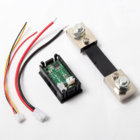
Need some help here for a builder. Any one seen this v/a type of meter? Screen name of builder is Sprin Go


Hi Regina,

Thank you for your previous answer, I got some thick wire and doing the wiring now.
According to somebody's wiring diagram from the forum, it says that the volt/amp meter has black, yellow and red wires.
Well, mine has blue, green and yellow.
As expected, I got no user's manual with it.
Can you please look at the photo below and try to figure out which wire is which?
Thanks a million in advance!
Dejan

20190115-123522.jpg


Sprin Go, Today at 3:44 A

Red + and black - might be power to the unit as in a couple monitors I have. Then if it light's up it must be power to the unit, then to find the voltage wire use a resistor like 1k or higher 4.7k or what ever you have to probe a nine volt battery to the other three wires to see which one makes the voltmeter read 9 volts. (take the - minus to ground first on the battery) most of these units use the yellow wire for volts. BUT since this unit has it paired with the green it may be the blue in this case. Using a resistor should not hurt anything in the meter to find out which one is the correct wire.
Then all that's left is the last two wires are for the current and I'm assuming they go to a shunt that came with this monitor as these wires are small and can't carry much current as such. Hook em up to the shunt and flip them if the reading is backwards or nil. Hope that is of some help. HB
 
Link to the forum post? I'm guessing one of those wires needs to output a range 0-5v for measuring drop across the shunt. Guessing blue. But where would you get voltage? Maybe it's I2C? I was just looking into building something like this.
 
The Thick Red and Black are for the voltage measurement across the shunt. Will have to get back to you on the others. Need to have a look at mine to see how its wired. It took me a bit of guess work as well. Lucky no damage.
 
The Thick Red and Black are for the voltage measurement across the shunt. Will have to get back to you on the others. Need to have a look at mine to see how its wired. It took me a bit of guess work as well. Lucky no damage.

But in this photo this one doesn't have the big thick red and black wires. I use one of those meters and the wires are very large because the meter has a internal shunt for reading up to 10 amps. (running solo no exterior shunt)

https://www.ebay.com/itm/Mini-DC-10...=item419f93926d:g:rZsAAOSwYHxWPWV-:rk:10:pf:0

They also offer it to read 50 / 100 amps with a external shunt.

https://www.ebay.com/itm/DC-100A-10...h=item41ada0eced:g:ysgAAOSwU3VbLz0a:rk:8:pf:0

"Well, mine has blue, green and yellow."

But now after rereading the post I think they just want to know about the other three wires. The blue, green, and yellow. If that's the case just probe them with a resistor and battery till you find the voltmeter wire. The other two wires are for the shunt. All else fails just buy 50 Amp one on EBAY with instructions they are cheap. .... HB
 

Attachments

  • meter-shunt.jpg
    meter-shunt.jpg
    110.5 KB · Views: 67
Hi Guys,

I started planning a build for an induction annealer a while back and stumbled onto this thread discovering that all my research was unnecessary as you guys essentially proved my idea would work... So thanks for such a great resource!

I have a technical question I'm hoping one of you might help with.

My build is slightly different in that in between my cheap Chinese PSU and the induction board, I'm using a DPS5020 (https://www.banggood.com/RUIDENG-DP...ply-p-1181200.html?ID=514816&cur_warehouse=CN) this is a buck converter essentially so I can do current and voltage limit/adjust (as well as it reads the draw) - very cool bit of kit for the price and certainly reduces some complexity in the design.

At the moment I'm also using an SSR to switch the power to the inductor, but the DPS5020 has a built-in on off for its output.... I remember reading somewhere it's important to have the supply ramp up fast for inductor resonance (hence my test used SSR to make sure components work) otherwise something will let out magic smoke?

I'd like to see if the DPS5020 is able to power on fast enough that I can skip the SSR (the DPS has a usb/serial interface that you can use to turn it on/off so i can simplify design if SSR not needed) - but I'm not sure how to test this and don't want to fry anything. I don't have access to an oscilloscope that I know of (which I have a feeling is the easy way to do this).. so alternatives on a postcard please :-)

if the oscilloscope is the only way could someone detail this test also (and I'll ask around the club see if anyone has one I can make use of).

Thanks again and kind regards

Tim
 

Upgrades & Donations

This Forum's expenses are primarily paid by member contributions. You can upgrade your Forum membership in seconds. Gold and Silver members get unlimited FREE classifieds for one year. Gold members can upload custom avatars.


Click Upgrade Membership Button ABOVE to get Gold or Silver Status.

You can also donate any amount, large or small, with the button below. Include your Forum Name in the PayPal Notes field.


To DONATE by CHECK, or make a recurring donation, CLICK HERE to learn how.

Forum statistics

Threads
165,800
Messages
2,203,692
Members
79,130
Latest member
Jsawyer09
Back
Top