• This Forum is for adults 18 years of age or over. By continuing to use this Forum you are confirming that you are 18 or older. No content shall be viewed by any person under 18 in California.

Induction brass annealer redux

Gina1 and Hollywood thank you for sharing you knowledge. Started building one last week to handle 50 BMG. Work coil design is being the most difficult part. I’m using .190 OD Tubing, 8 winds on 1” PVC pipe. Its drawing max 13.3 amp and taking 28 sec. I have tried 8 winds on 3/4” PVC and it is tripping my power supply at 16 amps. Any suggestions on getting the time down a little? Thanks again David

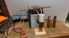
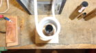
I have a spare induction board and wound a couple coils testing annealing 50 cal brass. I found that my white plastic pipe of 1.050 (just something I had) made the best annealing coil form for this brass with my circuit. The coils are 1/8 inch soft copper tubing. I may try testing a bit more on the turns but right now it is 10 turns. My power supply is 48 volts which I adjusted down to 45 volts. No brass draw is 7.5 amps, with brass annealing it is 15 amps and takes 10 seconds for slight red glow. I'm sure it can be fine tuned to a lower time but I don't shoot 50 cal, just trying to help out. A friend gave me 3 brass to test with. Here is a couple photos, notice my high tech/high current button that activates annealing. Also off to the right those are two 50 cal brass with one 6.5 creedmoor in the middle.
 

Attachments

  • annealing50cal1s.jpg
    annealing50cal1s.jpg
    171.5 KB · Views: 276
  • annealing50cal3s.jpg
    annealing50cal3s.jpg
    111.9 KB · Views: 244
Something new I've found lately is the 4 mm copper tubing. It has a inside dia of 3 mm (BIG) and will really move the water or coolant. 4 mm copper tubing is .157 OD and .118 ID compared to our normally 1/8 of .125 OD and .063 ID. A lot easier to move coolant! The 4 MM coil wound the way Gina and Erick suggest works just fine. I think the 4 mm will not load up the little coolant pumps with that small .063 restriction and run cooler, just food for thought. HB
 
Hypothetical question I have read this entire thread and not found the answer as yet so here goes.
If you had a 48V PS that could supply unlimited current ie never voltage drop. What happens re current level and induction board if a big hunk of metal is put in the middle of the coil? Does it blow up? Does it have a natural current limit? from what I have read it seems the insertion depth of a case dictates the current draw. But what happens when you really overload the work coil?
I have seen videos of these being used to melt some metals in a crucible.
 
The induction board has no limiting. Exceed its components' SOA and kaboom. This is why having a proper PSU with protective limiting is a sensible idea.
 
Personal experience........ It blew the board !! (blew... as in not working when power applied)
I once, and only once, managed to have a case drop into the coil a fraction off line and this caused it to lean against the coil causing a short. This completely destroyed the power supply even though it is supposed to have overload protection. Costly mistake.
 
Thats interesting but a bit worrisome as I have purchased an over-spec power supply as I always tend to over do things. I just wonder about the photos of the molten metal shown in the pictures advertising the product. They must have just the right amount of material not to draw to much current.
 
Welp, currently printing the stepper motor holders as well as the spacers for the linear rod screws holders up top.


table with steppers.jpg holder.png
 
Thats interesting but a bit worrisome as I have purchased an over-spec power supply as I always tend to over do things. I just wonder about the photos of the molten metal shown in the pictures advertising the product. They must have just the right amount of material not to draw to much current.

I would think having a current meter in the circuit, to monitor the current would help prevent over load, if you were using a crucible to melt metal. Amount, type of metal, how far into the coil, all will effect current draw.
 
Just make sure you have the ability to store the level/position of the shelf else all those steppers and screws will do no better than two fingers!

PS how do you ensure the two stepper motors stay in sync? Given the shelf weighs little you could just use one
 
I have most of the parts now they keep coming in dribs and drabs. Still cant do any little fiddling as the power supplies have not turned up yet. I will give the timer a test tomorrow using other power supplies. Most importantly the induction board tuned up today. On arrival one of the heat sinks was flapping in the wind and the mosfet was not screwed to the heatsink. Lots of cold solder joints. Removed both heat sinks absolutely no thermal compound had been used. The build quality is really crap overall.
 
Has anyone done a single shot unit with a trap door? Looking at the circuits if you use the B output it will stay open rather than a momentary time enough to drop a case and then close.
 
Not quite sure what you mean. I run my timer in single shot mode. It just needs to connect power to the trap door solenoid for 0.25s for it to open, allowing the case to fall and then close again when power is cutoff.

Sestos timer A = 5s (or whatever), B=0s, C=0.25s, D=0s

B is just a delay (as is D) and unconnected to a relay.
 
Hypothetical question I have read this entire thread and not found the answer as yet so here goes.
If you had a 48V PS that could supply unlimited current ie never voltage drop. What happens re current level and induction board if a big hunk of metal is put in the middle of the coil? Does it blow up? Does it have a natural current limit? from what I have read it seems the insertion depth of a case dictates the current draw. But what happens when you really overload the work coil?
I have seen videos of these being used to melt some metals in a crucible.

Just stick a 15 or 20 amp fuse inline to the board power and don't worry about it.It's a good idea to fuse it no matter what. I found some of the stand off/mounting holes are hot (40vdc went right to ground, loud pop) far as power on some boards and the fuse worked and saved the day... HB
 
Not quite sure what you mean. I run my timer in single shot mode. It just needs to connect power to the trap door solenoid for 0.25s for it to open, allowing the case to fall and then close again when power is cutoff.

Sestos timer A = 5s (or whatever), B=0s, C=0.25s, D=0s

B is just a delay (as is D) and unconnected to a relay.

Thats what I mean it just needs to be a short burst of power not a latched 12V to the solenoid. Looking at the Inkbird timer if run in single shot A is the programed 5s (or whatever) no voltage on B for that time then B turns on when A turns off latched until the reset.
 
Last edited:
Just stick a 15 or 20 amp fuse inline to the board power and don't worry about it.It's a good idea to fuse it no matter what. I found some of the stand off/mounting holes are hot (40vdc went right to ground, loud pop) far as power on some boards and the fuse worked and saved the day... HB

Good idea. There are only two types of faults. A open circuit and a short circuit. A fuse is good protection for the second type. We dont want the smoke to come out of the power supply.
 
The two boards (20A vs 50A) are different seems like. I can run mine (20A Sainsmart) at very high DC's at full load for long periods of time, heat sinks on the bottom and PCB temp controlled fan.

I notice that there has been a few builds made using Heat sinks under the board. I know there are some available that have heat transfer type stickers to hold them in place. But I was looking at just using old fashioned paste (not sure how to attach to board as yet).
Then I was also reading that the boards use a large ground plane as part of the circuit to obtain frequency. Has anybody noticed a change when applying the heatsinks.
Another concern I have with putting heatsinks on the bottom is the construction of the board looks like it has two halves in a layer of the board and placing a heatsink on one side would cause not issue I think but on the other side it would sit across the gap in the two halves. This could cause an issue changing the capacitance value. Again anyone notice and changes?
Sorry for all the questions I have read this entire thread at least 3 times have learnt a lot from everyone posting their experiences on what does and doesn't work. Hopefully my questions will help the next guy. When completed I will also be able to give back but then from an experience.
 
Paste => no stick You could use thermally conductive glue. Just plain easier to use heat sinks with thermally conductive tape already on. Remove backing and place. The ones identified by Grocmax fit within the gaps in the board between the solder points for the caps. Mouser part number:
532-374124B35G
 

Upgrades & Donations

This Forum's expenses are primarily paid by member contributions. You can upgrade your Forum membership in seconds. Gold and Silver members get unlimited FREE classifieds for one year. Gold members can upload custom avatars.


Click Upgrade Membership Button ABOVE to get Gold or Silver Status.

You can also donate any amount, large or small, with the button below. Include your Forum Name in the PayPal Notes field.


To DONATE by CHECK, or make a recurring donation, CLICK HERE to learn how.

Forum statistics

Threads
165,806
Messages
2,203,648
Members
79,130
Latest member
Jsawyer09
Back
Top