
You are using an out of date browser. It may not display this or other websites correctly.
You should upgrade or use an alternative browser.
You should upgrade or use an alternative browser.
Induction brass annealer redux
- Thread starter Gina1
- Start date


If fans are blowing all around, then the heat transferred by convection from air is minimal. You have no conduction as they don't touch, so that leaves radiation. You can insulate the copper tubes with that slip-on fiberglass sleeves, OR paint the copper tube with aluminum paint so its reflective of the radiant heat.At least then the heat rising from the caps isn't heating your copper and coolant
Another thing about using fans, its best if you can have flow-through-case ventilation across the component. Just stirring the air around helps some, but its far from optimal. Ducting will help. That was one of reasons I thought about the flexible cooling/conductor lines, so you could optimize flow through ventilation.
@#40Fan A test would be good - it would certainly help alleviate the fears of those (including BillK55) who are concerned about the adequacy of the pump coolant system. But do a rapid fire test of 100 cases as fast as you can feed them, measure the temp of your coolant pre and post, and tell us the volume of coolant you have. Repeat the test, with the same timing, once everything has cooled to ambient, but this time without the fan. As should be very clear from my posts over the last couple of days, I'm not worried about the temperature of the coil or the efficacy of the liquid cooling system. With some cheap/free initiatives heat transfer to the components cooled by the liquid cooling system can be minimised and the load on that system reduced significantly. I used Insultherm on the coil for three reasons: 1. first and foremost it allowed me to make a very tight coil without fear of shorting a turn (a tighter coil has more inductive power than a wider one with the same turns) 2. it minimises heat transfer from the hot cases taking a lot of load off the liquid cooling system and 3. it looks neater. I think it cost me $9 for 10 feet and I've done two coils and still have enough left over to do another 2-3 coils. Being a little smart about things like minimising the narrow portions of copper/plastic tubing to lower resistance to coolant flow, routing the copper sensibly (not directly over the cap furnace) and sleeving for the coil means you needn't worry so much about the liquid cooling typology.
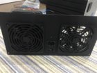
@BillK55 yes that's basically what I said. Heat transfer to the liquid cooling system is only via radiated heat with air as the conductor to the components in the cooling system (plus the transfer via the two direct contact points on the induction board). And the copper components are the most effective conductors to the coolant. A fan which just circulates hot air doesn't help that much. You need to blow cool air through the case. Almost my entire back panel is the intake vent. Hot air gets push out through venting in the top (and bottom) of the enclosure. I have attached a pic taken during the assembly process.
@BillK55 yes that's basically what I said. Heat transfer to the liquid cooling system is only via radiated heat with air as the conductor to the components in the cooling system (plus the transfer via the two direct contact points on the induction board). And the copper components are the most effective conductors to the coolant. A fan which just circulates hot air doesn't help that much. You need to blow cool air through the case. Almost my entire back panel is the intake vent. Hot air gets push out through venting in the top (and bottom) of the enclosure. I have attached a pic taken during the assembly process.
Attachments
Last edited:
In my setup the cooling from the radiator is not a problem, the fan RPM is low and I don’t bother regulating that fan.
The capacitor bank gets much hotter over time aNd its fan must go full blast eventually. I control this fan and it has a higher CFM/RPM rating than the radiator fan. The thermistor is wedged between two caps. I need put heat sinks on the copper buses as others have done.
The capacitor bank gets much hotter over time aNd its fan must go full blast eventually. I control this fan and it has a higher CFM/RPM rating than the radiator fan. The thermistor is wedged between two caps. I need put heat sinks on the copper buses as others have done.
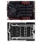
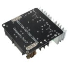
Despite Gina just standing there and watching me blub, blub, blub …… I did finally make it out of the deep end. I've started a little investigation on the difference between the 50A and 20A models of the ZVS. I first mentioned the 50A models seemed to have 8 caps, and the 20A's have 6. I looked at Ebay listings on each model until I found pictures where I could read the values on the capacitors (see attached examples).Doesn't matter how many caps are on it, just total capacitance
Dskogman reports that on his 50A model ZVS the eight caps are all 0.33 Mfd, the same 0.33 rating as the ones in pics I attached for both the 20A and 50A models. I had difficulty in looking at the pictures of bottoms of the two boards and being sure how they are networked, but my best guess is that they're all in parallel. From what I could gather from the link you posted about the resonant circuit, the frequency is a ratio of capacitance and inductance. So if the 50A model has 133% the capacitance of the 20A model. then if you use it with the same GinaEric coil (same inductance right?), won't it operate at 87% of the original frequency? Or is the inductance used in the frequency calculation a combination of inductors on the ZVS board and the work coil?
If with the 50A ZVS we are shifting the frequency that much then maybe we're not really getting the improvement in annealing that we'd have expected from the almost 1000W's his PS is delivering. He reports annealing 284’s at 3.2 sec at 35v, 27amp (950w). I will point out though his coil is 0.8" ID (I think same number of turns). Does smaller diameter, same turns, give higher inductance, so maybe he corrected for the frequency shift without realizing it (lol speak up Dskogman if you want to claim you did it on purpose).
I am pushing this discussion to help myself decide if the 50A ZVS and 1000W PS are beneficlal. Oh and btw I'm not worried ….. I'm wearing my handy life vest with the CO2 cartridges and auto-inflate pull cord.
Attachments

Doesn't matter how many caps are on it, just total capacitance, then need to know coil inductance. It can be calculated, however since capacitors have a wide tolerance (-/+ 5% and often more) measurement is the last word.
The lower the frequency the deeper the penetration into the workpiece, for thru heating of large pieces of steel they use low frequencies and gobs of power. 100KHz is about ideal for brass, around .010" penetration.
A greater number of caps for a given total amount of capacitance spreads the ripple load. (And of course increasing the capacitance bank for a given set of inductors and work coil will lower the oscillation frequency.)
I'm interested in why you think 100kHz is ideal for brass. PM me if more appropriate.
The more I look at these eBay boards the more I realise they are real PoS. If you step back a little a few things become apparent.
We have a liquid cooling system that is woefully under-utilised (rather than underspec'd which is the path Bill first started on). It is cooling only the work coil and our workpieces are heated relatively quickly and then promptly ejected. The cooling system passes directly over the most heat-generating parts of the system design yet it is not deployed to cool the components which most need cooling - the induction circuit MOSFETs and caps. Etc
We also have an induction board design which is quite likely generating a LOT more heat than it should be. For example, the MOSFETs have RdsOn of 40m ohms. It is the current flowing through this resistance which produces the heat that needs to be expelled by the MOSFETs. This could likely be cut to a small fraction of that with a better MOSFET choice. Then there's the capacitor bank. It (and the associated inductors) is quite likely not optimised for our application. It's great that the caps are metallized polypropylene film but the particular caps deployed are used in cookers at much lower frequencies. I can't find data on their ESR at particular frequencies. It is the greatest source of heat and we aren't using our liquid cooling system at all with it. The caps are also bunched together which inhibits cooling.
I think it is very instructive that the folks at EZ Anneal can have their induction board wrapped in a metal can (part used for heat sinking) with no fans anywhere near it.
Who is up for designing a better induction board?
")
Last edited:
Ya got me, I should have said QUICK DEPLOY@BillK55 Auto-inflate shouldn't need a pull cord.")
Boy this is going to take a little practice. Ever chemically welded acrylic/perspex? Sounds easy but it's so easy to make a mess of it. I decided to practice adding the ridges to my auto feeder disc which has suboptimal cutouts. Away from the disc I practiced a few times the technique of squeezing the applicator bottle before tipping it over etc. Then came the moment of truth. Poof! Sprayed the solvent straight across the disc. Just as well this is practice. I also used a little too much solvent on a couple of them. This stuff really does fuse rather than glue.
Attachments

I've never done it myself, but I remember someone explaining to me how they did it, and it makes me wonder if maybe in certain situations different techniques work better. Rather than squirt the solvent out on one piece then stick the two parts together, try holding the two pieces in place, then apply the solvent at the interface between the two parts. It was my understanding that the solvent would wick into the gap, one of those surface tension tricks, and just a little drop would go along way. You may end up with a little cosmetic blemish at the application point. I, don't know if a quick wipe would take care of it, or you may just be stuck with that little blemish. Could also be its a scale up thing, I don't know how far the solvent can wick, so for a larger piece using this technique you might have to make several application points around the perimeter. The wicking distance is going to be in part a function of how smooth the interface is between the two parts. The person I was talking to was actually bonding clear acrylic parts, so the two surfaces were highly polished, but it was amazing that after it was done the interface practically disappeared.Then came the moment of truth. Poof! Sprayed the solvent straight across the disc.
Yes that is how it is done. You aren't gluing but rather chemical welding. The solvent has a water-like viscosity. The technique is easy to explain (not conceptually difficult) but takes some practice. Didn't notice that tiny bit of solvent on the outside of your needle before you inverted the applicator? Piece permanently marred.
Spill or drip? You cannot wipe. Damage done, wiping makes it worse.
But get it right and it looks like there isn't a join at all.
Spill or drip? You cannot wipe. Damage done, wiping makes it worse.
But get it right and it looks like there isn't a join at all.
@SGK Ok I misunderstood you. Was thinking you meant when you tipped over the piece, but it was the applicator you were tipping. Yes that slosh of tipping or slight accidental squeeze as you adjust your hand can make thin liquids squirt out that little tip.
Not sure how to connect it up to your applicator, but if you can take a piece of that thin capillary tubing that's used as the dip pipe in a nasal spray bottle and attach it as the tip of your applicator, it may give you more control. Its got a tiny bore so there's not much volume and you can see the fluid coming as it approaches the end of the tube.
Not sure how to connect it up to your applicator, but if you can take a piece of that thin capillary tubing that's used as the dip pipe in a nasal spray bottle and attach it as the tip of your applicator, it may give you more control. Its got a tiny bore so there's not much volume and you can see the fluid coming as it approaches the end of the tube.
So I thought I would post a view previews of the autofeeder I am working on. The idea behind this is that it could sit atop any annealer unit with a wide enough lid to support it**, positioned such that the drop tube aligns with the induction coil (the tube could even sit in the coil).
** The base is 10in wide (as is the hopper). The base is designed such that the centre of the drop shoot can extend up to 56mm (2.2") forward of whatever the feeder is sitting on. It could probably go a bit further than that with the 'feet' partially over the edge.
You can see the design via this link: https://a360.co/2OvYT8M
(That web view is designed for collaborative working and so if, from time to time, I am working on the design and have saved it with some of the components' visibility turned off you won't get the whole picture, but it is a funky way of sharing it here.)
The "hopper" is simply one of these ($12.49): https://www.amazon.com/gp/product/B0012GVYRO/?tag=accuratescom-20
And 5rpm motor ($14.99): https://www.amazon.com/gp/product/B071XCX778/?tag=accuratescom-20
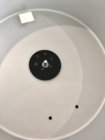
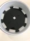
As I was unsure of how thick the aluminium of the cake tin was going to be I designed a motor mount in 3mm acrylic (about $5 or less). I will probably do this again in acrylic half as thick. It may not even be necessary as the aluminium is about 1.5mm thick but I think still a good idea and, if nothing else, it provided a template for marking the motor holes.
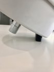
The first pic shows the drilled hopper (without holes for the 'drop shoot' screws at this stage). The second with the motor and motor mount fitted. The third shows the fitted feeder disc. I have to check cost but I think one of these discs would about $25 each and the couplings are these ($5.99): https://www.servocity.com/0-770-set-screw-d-hubs. The D-hubs are better than plain circular ones. The fourth pic shows the hopper sitting on the 3D printed rear pedestal. I haven't yet had the base plate manufactured but the design is done. One base and one feeder disc could be cut from a single piece of acrylic. As mentioned a couple of posts up, the bumps in the feeder disc are solvent fused to the disc with Weldon 3. There's enough solvent in one of those cans to do countless discs if you don't let it evaporate.
The next step is to order the 'drop shoot' which connects the hopper to the (20mm OD 16mm ID) clear acrylic drop tube (eBay $5.52 and likely long enough for two builds). This drop shoot is the most expensive part as it needs to be printed via Selective Laser Sintering. Like anything else, there are economies of scale when it comes to getting these things made. I am about to order two as I am doing two builds. The last pic shows the clear tube and the 3D printed clamp. The hopper is screwed to the rear pedestal, and the pedestal screwed to the base. At the front, the drop shoot screws to the hopper, slides over the top of the drop tube and the drop tube slides through the base and is held at the correct height by the 'clamp'. Currently I haven't provided for screws between base and clamp as I didn't think them necessary - if you guys think I am wrong do let me know! The pedestal and clamp printed via FDM cost $20 plus delivery.
Control of the autofeeder is very simple. When a case is detected in the coil via an IR switch, power is cut to the feeder. When the case clears through the trap door, power to the feeder is restored.
The manual work associated with this build thus far is just drilling the hopper and countersinking the motor mount and feeder disc holes. I used a hand fret saw (https://www.amazon.com/gp/product/B00MJXTT5S/?tag=accuratescom-20) to rough cut the drop aperture and refined it with a needle file (https://www.amazon.com/gp/product/B07CMY4P3L/?tag=accuratescom-20). As I am useless at making almost anything I had the clamp and pedestal printed. Someone more capable could make these by hand. It is only important to get the slope of the pedestal correct (30 degrees) as the geometry of the drop shoot is linked to this. (In the design model I can change this angle and the shape of the drop shoot adjusts accordingly.)
If people are interested in also pursuing this feeder let me know. I think I can set up the acrylic parts for sale via the cutting service I am using. (They don't charge a sales fee. Just the cost of manufacture and delivery. So that's efficient.) I can also advise regarding getting the drop shoot etc made once I finalise them.
** The base is 10in wide (as is the hopper). The base is designed such that the centre of the drop shoot can extend up to 56mm (2.2") forward of whatever the feeder is sitting on. It could probably go a bit further than that with the 'feet' partially over the edge.
You can see the design via this link: https://a360.co/2OvYT8M
(That web view is designed for collaborative working and so if, from time to time, I am working on the design and have saved it with some of the components' visibility turned off you won't get the whole picture, but it is a funky way of sharing it here.)
The "hopper" is simply one of these ($12.49): https://www.amazon.com/gp/product/B0012GVYRO/?tag=accuratescom-20
And 5rpm motor ($14.99): https://www.amazon.com/gp/product/B071XCX778/?tag=accuratescom-20
As I was unsure of how thick the aluminium of the cake tin was going to be I designed a motor mount in 3mm acrylic (about $5 or less). I will probably do this again in acrylic half as thick. It may not even be necessary as the aluminium is about 1.5mm thick but I think still a good idea and, if nothing else, it provided a template for marking the motor holes.
The first pic shows the drilled hopper (without holes for the 'drop shoot' screws at this stage). The second with the motor and motor mount fitted. The third shows the fitted feeder disc. I have to check cost but I think one of these discs would about $25 each and the couplings are these ($5.99): https://www.servocity.com/0-770-set-screw-d-hubs. The D-hubs are better than plain circular ones. The fourth pic shows the hopper sitting on the 3D printed rear pedestal. I haven't yet had the base plate manufactured but the design is done. One base and one feeder disc could be cut from a single piece of acrylic. As mentioned a couple of posts up, the bumps in the feeder disc are solvent fused to the disc with Weldon 3. There's enough solvent in one of those cans to do countless discs if you don't let it evaporate.
The next step is to order the 'drop shoot' which connects the hopper to the (20mm OD 16mm ID) clear acrylic drop tube (eBay $5.52 and likely long enough for two builds). This drop shoot is the most expensive part as it needs to be printed via Selective Laser Sintering. Like anything else, there are economies of scale when it comes to getting these things made. I am about to order two as I am doing two builds. The last pic shows the clear tube and the 3D printed clamp. The hopper is screwed to the rear pedestal, and the pedestal screwed to the base. At the front, the drop shoot screws to the hopper, slides over the top of the drop tube and the drop tube slides through the base and is held at the correct height by the 'clamp'. Currently I haven't provided for screws between base and clamp as I didn't think them necessary - if you guys think I am wrong do let me know! The pedestal and clamp printed via FDM cost $20 plus delivery.
Control of the autofeeder is very simple. When a case is detected in the coil via an IR switch, power is cut to the feeder. When the case clears through the trap door, power to the feeder is restored.
The manual work associated with this build thus far is just drilling the hopper and countersinking the motor mount and feeder disc holes. I used a hand fret saw (https://www.amazon.com/gp/product/B00MJXTT5S/?tag=accuratescom-20) to rough cut the drop aperture and refined it with a needle file (https://www.amazon.com/gp/product/B07CMY4P3L/?tag=accuratescom-20). As I am useless at making almost anything I had the clamp and pedestal printed. Someone more capable could make these by hand. It is only important to get the slope of the pedestal correct (30 degrees) as the geometry of the drop shoot is linked to this. (In the design model I can change this angle and the shape of the drop shoot adjusts accordingly.)
If people are interested in also pursuing this feeder let me know. I think I can set up the acrylic parts for sale via the cutting service I am using. (They don't charge a sales fee. Just the cost of manufacture and delivery. So that's efficient.) I can also advise regarding getting the drop shoot etc made once I finalise them.
Attachments


Last edited:
How many volts are you guys getting across the induction board when it is supplied with power? (i.e. the 48V PSU is loaded by the induction board)
I'm just doing some testing without a coil installed. I have 48V at the PSU with no load, but when the supply is loaded with the induction board (no coil attached) this drops to 10V (current limited at 11A).
Maybe it's because I don't have a connection between +/- out of the induction board. Hmm...
EDIT
Yup. Added the coil (without soldering it in just yet) and got 35V/12A with a 308 case in the coil. I wonder if/how much that drop of 13V will fall if the coil is properly soldered in place.
Last edited:

Testing Bluetooth link to my control board. (No NTCs attached yet and hence the temps are -79.) The little module is one of these: https://www.amazon.com/gp/product/B06WGZB2N4/?tag=accuratescom-20
Also, would be very easy to use the board and this interface to replace the Sestos timer, store presets etc.
Last edited:
I'm appealing to the more EE-ish of you. Back to the comparison of the 20A vs 50A ZVS boards. As I said before in general the 20A models have six 0.33 mFd capacitors and the 50A versions have eight also 0.33 mFd. I was thinking about it in terms of how the operating frequency of the two ZVS's would compare if both were using the same standard GinaEric coil. I took the formula that I think GrocMax had given me the link to, and came up with that the ratio of the Freq_50A/Freq_20A is inversely proportional to the square root of the two units capacitances. I came up with the Freq_50A would be (6/8)^0.5 or 87% of the frequency the 20A unit, and we know from GrocMax's measurement the 20A unit runs at over 100 kHz. I was concerned that dropping the frequency down into the 80's kHz range might hurt the annealing efficiency. I THINK I made an erroniomous assumption though. Do not the wire wound torroids also contribute inductance (its not just the tubing coil) in this calculation I was trying to do? Since I don't have a board yet, I'm just looking at pictures, but the torroids on the 50A ZVS look larger diameter and appear to have more wraps of wire, so its possible (lol again maybe a terrible assumption) they could have ratio'd up the board side of the inductance as well as capacitance, so the L/C ratio is the same on both units.
Is there anyone with a 50A ZVS that has measured the frequency and with what coil?
And just as curiosity, has anyone measured the frequency running with the 1/4" stock coil that COMES WITH the 20A ZVS?
Oh and another tidbit noticed along the way. Both the 20A and 50A ZVS's (at least all checked so far) have 50 kHz rated capacitors, so the fact in our application that the capacitors and board underneath them overheat and are the locus of common board failures is probably expected. We're running them at 200% of spec.
I know, I know, just add the fan and heatsinks, run it slow and easy, or pause to let it cool down when your temp alarm goes off, and it'll be fine. We're taking an inexpensive commonly available item and putting it to a specialized use. We asked for it. Its not going to be me, but some industrious person that wants to run a gazillion cases per hour might want to modify some of the limiting links in the design.
Again, I'm not bashing the GinaEric. Hats off again to Gina and Hollywood!
Oh and another tidbit noticed along the way. Both the 20A and 50A ZVS's (at least all checked so far) have 50 kHz rated capacitors, so the fact in our application that the capacitors and board underneath them overheat and are the locus of common board failures is probably expected. We're running them at 200% of spec.
I've not seen a "frequency rating" for a capacitor before. Nominal capacitance and ripple rating, yes, "frequency rating", no. Capacitive reactance - in a perfect world - falls with increased frequency but parasitic ESR and ESL mean a capacitor's reactance (loosely, the complex equivalent of resistance) takes on a U shape versus frequency. Perhaps you mean that 50kHz is where reactance is minimised or perhaps more probably this is the frequency for which the manufacturer has provided reactance data because that is the 'frequency of design' of applications for its intended use? It is the AC ripple running through the ESR that causes heat. And ESR varies with frequency.
http://www.eenewseurope.com/news/understanding-capacitors-ripple-and-self-heating


I just received some cool parts
I reckon I got the "fit" with the Amazon cake tin hopper almost perfect. The sleeve fit over the 20mm OD tube was another question. I was advised by the guy who made the drop shoot parts to have 0.5mm extra diameter. I reckon this could have been lowered to 0.25mm or perhaps even less. Even so the fit is very good.
Now to place the three holes in the "hopper" to attach it. Plus get the base cut.
Last edited:
I've not seen a "frequency rating" for a capacitor before.
Look on your ZVS board on the top edge of one of the capacitors. There are 3 lines of writing, its the middle line. The left end of the line has the 0.33 mFd. Now look at the other end of that line. I'm looking at a picture zoomed way it, so its getting fuzzy. but the right end of the line looks like it says 50 (something)Hz. I've been thinking it was kHz. dskogman read on his 50A board and also thought it said 50 kHz, but when I looked again just now it almost looked like NHz. Nano Hertz? That doesn't make sense. Its definitely Hz, but its the letter in front of it in question.
Last edited:
It does say SH50kHz. (I suspect the SH merely stands for Self Healing a property of the dielectric.) You can find these things on the web very easily. Just Google MKPH-SH induction capacitors. However the data sheets have little to no real info about things such as dissipation factor by freq etc. I suspect, still, it is incorrect to think of this as a "rating". I could be wrong. All that said, the dissipation factor of an MKP capacitor rises sharply with frequency, meaning more heat with higher freq.
You can knock yourself out with some light reading such as https://en.tdk.eu/download/530754/4...1513474ba/pdf-generaltechnicalinformation.pdf
You can knock yourself out with some light reading such as https://en.tdk.eu/download/530754/4...1513474ba/pdf-generaltechnicalinformation.pdf
Similar threads
- Replies
- 74
- Views
- 47,372
- Replies
- 0
- Views
- 1,576
Upgrades & Donations
This Forum's expenses are primarily paid by member contributions. You can upgrade your Forum membership in seconds. Gold and Silver members get unlimited FREE classifieds for one year. Gold members can upload custom avatars.

Click Upgrade Membership Button ABOVE to get Gold or Silver Status.
You can also donate any amount, large or small, with the button below. Include your Forum Name in the PayPal Notes field.
To DONATE by CHECK, or make a recurring donation, CLICK HERE to learn how.
Click Upgrade Membership Button ABOVE to get Gold or Silver Status.
You can also donate any amount, large or small, with the button below. Include your Forum Name in the PayPal Notes field.
To DONATE by CHECK, or make a recurring donation, CLICK HERE to learn how.