Install the app
How to install the app on iOS
Follow along with the video below to see how to install our site as a web app on your home screen.
Note: This feature may not be available in some browsers.
You are using an out of date browser. It may not display this or other websites correctly.
You should upgrade or use an alternative browser.
You should upgrade or use an alternative browser.
Induction brass annealer redux
- Thread starter Gina1
- Start date
As a practical matter, have you ever looked at how many times the induction board switches off/on during that 1.88s? Your duty cycle would have a maximum of a bit less than 100x a second (given computational time). I wonder how much in practice the temp of the brass moves more than +/- 2% (I think this is your toggle margin) during such a period.
Since the feed back check is activated every 10 milliseconds + computation time, theoretically the maximum SSR switching should be <=188 times. The 10 milliseconds period was selected to be higher than the ON/OFF timing capabilities of the SSR.
I current the toggle margin is +/- 2.5% for additional SSR relief.
Keep in mind that the number of ON/OFF switching is function of the heat inertia of the brass.
Yes, in the heating routine, I average (smoothing) the readings every 100 loops.
I just wonder how the number of ON/OFF switching affects memory usage?
The on or off times of the SSR should never be at the limits of their minimum switching times. That would have the MOSFETs inside the SSR in the transitions period for a large percentage of the time, overheating it, leading to failure. Better to the minumum on of off time period 5x+ more than the minimum switching time.
Mine SSR Potter and Brumfield
ON - 0.6 millisecond
OFF - 2.6 millisecond
ON - 0.6 millisecond
OFF - 2.6 millisecond
What micro are you using? I'm using an Atmega 328p it has 32K rom and 2K ram. I think I may be able to squeeze in Freertos, UI with LCD display and rotory encoder. Not much ram to store tuning data that would have to dumped out the USB/serial port.
I'm using a PIC and an old one at that. A PIC16F1829 embedded in a custom board I designed for my build. I'm now pushing it all to the limit.
Since the feed back check is activated every 10 milliseconds + computation time, theoretically the maximum SSR switching should be <=188 times. The 10 milliseconds period was selected to be higher than the ON/OFF timing capabilities of the SSR.
I current the toggle margin is +/- 2.5% for additional SSR relief.
Keep in mind that the number of ON/OFF switching is function of the heat inertia of the brass.
Yes, in the heating routine, I average (smoothing) the readings every 100 loops.
I just wonder how the number of ON/OFF switching affects memory usage?
It doesn't. But all my code and functionality has to fit on the PIC. As I add more functionality I consume more program memory. Without activating a sensor and using every trick I can to reduce computation complexity I'm at 97.4% program memory. Were I to start anew I'd design a daughter board for an Arduino rather than the board for the PIC. But I should have enough to get everything I want out of it, maybe. One casualty may be my 'annealing' LED. At the moment I simply moved the one on the induction board to the front panel. Power to induction board and the 'annealing' light on the front panel illuminates. Switching to pulling the gates low to turn the induction board off means 48V is always connected to it and so the annealing LED is permanently lit. I don't think I will have a spare pin on the PIC to operate an additional LED.
Ideally your smoothing would be a moving average - each new reading displaces the first.
It occurs to me that the flame sensor is likely a poor choice for this application - yet a better mousetrap than one without. As noted already, it's peak sensitivity is for wavelengths very different from ideal. Also, importantly, these things are unlikely to be temperature stable - meaning their response changes as the ambient temperature changes. (This will be particularly acute if the sensor is close to the work coil.) A better way surely lies in using a thermopile sensor. But that can be an exploration for some other day.
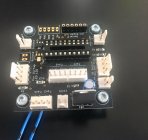
An old pic of top side of my control board is below. There's lot more SMD parts on the bottom side. The PIC is not in place in this photo. Switch 1 controls power to my autofeeder. Empty "switch 2" now controls my trap door solenoid. The Sestimer functionality is now being done by the PIC (should have done this from the outset) which required a small hack to the board on the underside. I connect to the board via an HM-10 Bluetooth module that sits in the serial connections.

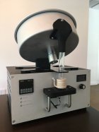
Old pic of my annealer (before I wired up the auto feeder). Obviously the Sestimer has now been removed. I will have a plate supporting the holder of my flame sensor over that area. I will likely have to make some mods to my auto feeder (although I tend not to use it tbh).

(Note to new builders: don't bother with the current limiter. Mine is always set for full current. You want a big burst of focused energy not a dribble.)
Last edited:
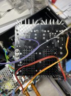
So I switched my annealer over to pulling the induction board gates low to turn the board off - this time with the Schottky diodes (duh). Seems to work just fine based on the limited testing I've done. Much better than switching 48V high current to the induction board. The image below shows the connections (purple and grey wires) to the solder pads of the induction board's R1 and R2 - the sides closest to the board's HEXFETs. I'm pretty sure anyone can manage this mod to the board.

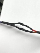
On the other end of these wires I attached the two Schottky diodes (part 1N5818) to isolate the two. Ground these two wires however you see fit (Arduino, controller, Sestos timer) and the board will turn off. No need for an automotive relay etc.


On the other end of these wires I attached the two Schottky diodes (part 1N5818) to isolate the two. Ground these two wires however you see fit (Arduino, controller, Sestos timer) and the board will turn off. No need for an automotive relay etc.

Last edited:
That is exactly what I'm doing. No big memory loss.Ideally your smoothing would be a moving average - each new reading displaces the first.
I wonder what the top rated manufactures of brass annealing machines are using. So, one day we all benefit from your exploration. For now this is our choice.It occurs to me that the flame sensor is likely a poor choice for this application - yet a better mousetrap than one without. ....thermopile sensor. But that can be an exploration for some other day.
The ambient light is the only factor (VenatusDominus ). The ambient temperature in the room is not.be temperature stable - meaning their response changes as the ambient temperature changes.
At the end, your built outside looks very professional (I'm little envious) .
God luck
Agreed it's the best mousetrap we have for now. Industrial machines certainly aren't holding cases at 1000F for 1.88s which bugs me a bit. Radyne's units can do up to 320 cases a minute. You can find videos of their machines in operation on Youtube but I'm trying to find once again a video I saw of another commercial unit that had a close up of their induction parts operating. If I do find it I will publish the link. Again, the cases were moving through the 'work coil' very quickly.I wonder what the top rated manufactures of brass annealing machines are using. So, one day we all benefit from your exploration. For now this is our choice.
Thermopiles are what high-temp infrared thermometers use. A smarter cookie than me could probably hack a modest cost high-temp infrared thermometer and use the readings from it. Thermopiles measure both ambient and object temperature (exploiting the Seebeck effect).
The ambient light is the only factor (VenatusDominus ). The ambient temperature in the room is not.
It's a transistor and like any transistor it will have a response that moves with ambient temperature. If you look at the data sheets for other phototransistors on, say, Mouser you will see what I mean. The Ic current is not linear with ambient temperature. The 10k emitter resistor helps to stabilize it. Unfortunately SunRom don't publish a proper datasheet.
At the end, your built outside looks very professional (I'm little envious) .
Thanks. Pretty can be very constraining when it comes to making modifications for improvement however.
EDIT: datasheet for the YG1006 (see Fig 3)
YG1006 Datasheet
Last edited:
You might be interested in this little Arduino project https://circuitdigest.com/microcont...meter-using-arduino-and-ir-temperature-sensor Unfortunately the particular sensor used only has a range up to 382C but it is an indication of what might be possible to measure case temp more accurately. It would be interesting to open up one of these https://www.thermoworks.com/ir-gun/...Gwk6Wg5uH85JB4QPXz5Z_e1rnwI5cdpkaAnZxEALw_wcB which is capable of reading to 1022F (and is relatively cheap).
Another question. Someone was measuring the current (I presume input to the ZVS) while annealing. I would think that the current isn't constant but sinusoidal matching the oscillation freq. about 100 kHz. Since most of us won't be using a high speed ADC or Micro that has the power to process this, only a rough estimate of the current can be inferred.
Using one of those low cost IR guns to calibrated your flame sensors seems like a good compromise.
I found that Arduino IR project before while looking for way to monitor the air cooled induction coil temp. Thinking about using an IR sensor or therocouple attached to the coil. The coil's insulation breakdown is around 250C so I would stop somewhere below 200C. I don't know how many cases per hour an air cooled coil could do, but I'm not concerned if I don't have to babysit the machine while it works.You might be interested in this little Arduino project https://circuitdigest.com/microcont...meter-using-arduino-and-ir-temperature-sensor Unfortunately the particular sensor used only has a range up to 382C but it is an indication of what might be possible to measure case temp more accurately. It would be interesting to open up one of these https://www.thermoworks.com/ir-gun/...Gwk6Wg5uH85JB4QPXz5Z_e1rnwI5cdpkaAnZxEALw_wcB which is capable of reading to 1022F (and is relatively cheap).
Using one of those low cost IR guns to calibrated your flame sensors seems like a good compromise.
Another question. Someone was measuring the current (I presume input to the ZVS) while annealing. I would think that the current isn't constant but more like a half wave retified sinewave matching the oscillation freq. about 100 kHz. Since most of us won't be using a high speed ADC or Micro that has the power to process this, only a rough estimate of the average current can be inferred.
Last edited:
I have one of those (waist of money). Both devices use lenses that cannot focus on the case neck. The first one is built with Gravity sensor , which is similar to one I use. For our applications the tempilaqe is the king (don't leave home without it +/- 2 % accuracy).You might be interested in this little Arduino project https://circuitdigest.com/microcont...meter-using-arduino-and-ir-temperature-sensor Unfortunately the particular sensor used only has a range up to 382C but it is an indication of what might be possible to measure case temp more accurately. It would be interesting to open up one of these https://www.thermoworks.com/ir-gun/...Gwk6Wg5uH85JB4QPXz5Z_e1rnwI5cdpkaAnZxEALw_wcB which is capable of reading to 1022F (and is relatively cheap).
Last edited:
The high oscillation is within the tank circuit. The current draw from the PSU is very linear and increases as the brass heats to Curie temp. There is a sinusoidal aspect but around a very narrow band around a very linear path. (You can examine this in LTspice.)Another question. Someone was measuring the current (I presume input to the ZVS) while annealing. I would think that the current isn't constant but more like a half wave retified sinewave matching the oscillation freq. about 100 kHz. Since most of us won't be using a high speed ADC or Micro that has the power to process this, only a rough estimate of the average current can be inferred.
Last edited:
I have one of those (waist of money). Both devices use lenses that cannot focus on the case neck. The first one is built with Gravity sensor , which is similar to one I use. For our applications the tempilaqe is the king (don't leave home without it +/- 2 % accuracy).
As I said, it's indicative of what one could do. There was only one built in the project. The sensor used in the build (https://www.melexis.com/en/product/MLX90614/Digital-Plug-Play-Infrared-Thermometer-TO-Can) is extremely accurate and a fully integrated solution (not just a thermopile) but caps out at 380C or thereabouts so it doesn't work for our application but others are available. The 'focus' depends on the field of view of the thermopile. It doesn't 'focus' per se. (The laser is just a pointer.) A narrow field of view sensor would be required. The Sunrom phototransistor has a very broad 60 degree field of view. You can get thermopiles with a 10 degree view. (Of course Tempilaq tells you you've hit temp but not whether you've gone over. And then you've still got to hope your sensor is stable else you are back using Tempilaq for every case.)
I'm wondering how this plays out in reality. By that I mean how long does it actually take for brass to cool 2.5%? Does it cool within 10mS (and so your duty cycle is close to 100Hz) or actually much slower because it takes more than 10mS to cool. I would have thought it would take longer to cool but perhaps I am wrong. You could test this easily by having your Arduino count the toggles.Since the feed back check is activated every 10 milliseconds + computation time, theoretically the maximum SSR switching should be <=188 times. The 10 milliseconds period was selected to be higher than the ON/OFF timing capabilities of the SSR.
I current the toggle margin is +/- 2.5% for additional SSR relief.
Last edited:
Someday I would do that out of curiosity. Again, the less toggles the less work for the SSR and it all depends of the mass of the brass and the cooling airflow throughout the built, not to mention the temperature of the shop. So, I see no use of this number.You could test this easily by having your Arduino count the toggles.
Sorry for the late replay, I was on vacation last week and did not have my annealer with me. The coil is double wound around a .65" tube. The inner winding is 3.5 turns and the outer is 3 turns. The red covering is Uxcell insulation sleeve 3mm I found on Amazon, it is a fiberglass and silicone heat shield used to allow for a tight coil wind without the coils touching each other. Let me know if you have any other questions.
@VenatusDominus Do you know what frequency your annealer is operating at? (If, yes, are you using the 'standard' Induction board with 1.98uF of capacitance?)
Induction coil ??
@VenatusDominus provided a formula for Henries given coil dimensions. If I recall correctly the Henry value for inductors in series is additive. I believe it was suggested for a multilayer coil to average the diameter. So, if I have a 3 layer 3-1/2 turn coil with the length being .625" - averaging the diameter would be .87". The value would be .228 uH. If I took each layer separately they would be .1062uH, .228uH and .3737uH. If I add them together it would be .7079uH. If I took the average and multiplied by 3 it comes out .684uH. Close to the additive value. If each layer had a different number of turns I don't see how the averaging method would work.
I believe the goal is about 1uH so the above example is no good (unless I want the frequency to be higher).
What is the correct method to determine uH?
Click to expand...
Coil32 - Multilayer air core coil
Formulas and new method for calculating multilayer inductor.
The discussion at the link above and the calculator provided here:
Coil32 - Multilayer coil calculator
Multilayer air core coil inductance calculator by Maxwell's method.
suggest that to get to the circa 1.1uH of the GinaErik basic work coil would require about 8 turns (3 layers) with 1/8" (.3175cm) copper tubing and a 0.65" (1.65cm) diameter mandrel.
Last edited:
I am using the "standard" induction board with 1.98uF capacitance. My coil is 2 layer with 6.5 turns and calculated at 122 KHz@VenatusDominus Do you know what frequency your annealer is operating at? (If, yes, are you using the 'standard' Induction board with 1.98uF of capacitance?)
Coil32 - Multilayer air core coil
Formulas and new method for calculating multilayer inductor.
coil32.net
The discussion at the link above and the calculator provided here:
Coil32 - Multilayer coil calculator
Multilayer air core coil inductance calculator by Maxwell's method.coil32.net
suggest that to get to the circa 1.1uH of the GinaErik basic work coil would require about 8 turns (3 layers) with 1/8" (.3175cm) copper tubing and a 0.65" (1.65cm) diameter mandrel.
Calculated.Thanks. Calculated or measured?
Similar threads
- Replies
- 74
- Views
- 47,355
- Replies
- 0
- Views
- 1,576
Upgrades & Donations
This Forum's expenses are primarily paid by member contributions. You can upgrade your Forum membership in seconds. Gold and Silver members get unlimited FREE classifieds for one year. Gold members can upload custom avatars.

Click Upgrade Membership Button ABOVE to get Gold or Silver Status.
You can also donate any amount, large or small, with the button below. Include your Forum Name in the PayPal Notes field.
To DONATE by CHECK, or make a recurring donation, CLICK HERE to learn how.

Click Upgrade Membership Button ABOVE to get Gold or Silver Status.
You can also donate any amount, large or small, with the button below. Include your Forum Name in the PayPal Notes field.
To DONATE by CHECK, or make a recurring donation, CLICK HERE to learn how.


