You are using an out of date browser. It may not display this or other websites correctly.
You should upgrade or use an alternative browser.
You should upgrade or use an alternative browser.
Induction brass annealer redux
- Thread starter Gina1
- Start date
I'll give that a shot...found some on ebay for 99 cents each and 99 cents shipping from Reno! Doesn't get better than that...The pot I changed to is a Bourns 3266W 12 turn. Much finer adjustment.
Notice the base of the IR led plastic has a flat (cathode) on the + side.

Bourns 3266 PV37- 50 kOhm - 1/4" Square 12 Turn Trimpot Trimming Potentiometer | eBay
Find many great new & used options and get the best deals for Bourns 3266 PV37- 50 kOhm - 1/4" Square 12 Turn Trimpot Trimming Potentiometer at the best online prices at eBay! Free shipping for many products!
www.ebay.com
Any tips on how it gets connected?
Also, I can run the whole sensor assembly on 5 volts or 3.3 volts (been using 5) ...any input on whether one would be better than the other?
itchyTF
Gold $$ Contributor
The 3266 and PV37 are different series according to Bourns. BRIEFLY looking at the datasheets I didn’t see any major differences. The original pot on my flame sensor is 10k. 50k might also work.
As long as the pins are arranged in the triangle configuration, just remove old pot and put in new.
Since the relay board uses 5v (5v coil) I would stick with that for the flame sensor.
As long as the pins are arranged in the triangle configuration, just remove old pot and put in new.
Since the relay board uses 5v (5v coil) I would stick with that for the flame sensor.
Re: Post #2410 - Quoting VenatusDominus
"This is easy to plug into Excel and if you pick 810.9 K (1000 F) for your target temp you will anneal in 1.88 seconds. Note that brass starts to glow between 950 F and 1050 F. Using 900 F changes the required time to 16.1 seconds.
B=1.38065x10^-23 (Boltzmann constant)
E=0.327x10^-18 (constant for the material, in this case brass)
T1 in Kelvin = 644 (700 F)
t1 in sec = 3600 (1hour)
T2 in Kelvin = target temp
t2 in sec = time to anneal
t2=t1*exp^(-E/B*(1/T1 - 1/T2)) "
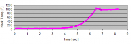
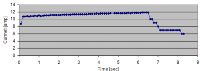
I consider the formula to be accurate. Following this lead I added a flame sensor to my built. The sensor was calibrated at 1000 F with the help of 1000 F Tempilaq liquid. My Arduino program was modified to include closed temperature feedback loop.
This way I was able to apply power (ON-OFF ) to the brass, maintaining the temperature of the neck at 1000 degree F (+/- 2-3%) for a limited time of 1.88 seconds (as per the formula).
The ZVS primary current and neck temperature readings are
averaged for each interval of 1/10 of sec (see the actual numbers attached).
As result, during the period of 1.88 seconds, with constant 1000F temperature, the neck color is fairly consistent. On the diagram, provided by SGK in Post # 2733, the color is between 930 F and 1050 F.


Attachments
Could you be more specific? It would benefit all of us, who are using flame sensors or planning to use one.Wrong formula? Wrong interpretation? Decimal in the wrong place?
Thanks
itchyTF
Gold $$ Contributor
I was trying to find a correlation between IR wavelength and temperature. The flame detectors are supposed to detect between 760nm and 1100nm. I wanted to find out what that means in terms of temperature.Could you be more specific? It would benefit all of us, who are using flame sensors or planning to use one.
Thanks
There's a formula (Wien's) rearranged that states - temp(K) = proportionality constant / T(K ). Constant is .002898m or go to https://www.omnicalculator.com/physics/wiens-law
This has to do with black bodies so maybe that's not applicable.
According to the formula 760nm = 6,400F and 1,100nm = 4,280F.
This is way beyond the dim red glow that happens around 900-1,000F yet the sensor picks it up.
Based on this information:I was trying to find a correlation between IR wavelength and temperature. The flame detectors are supposed to detect between 760nm and 1100nm. I wanted to find out what that means in terms of temperature.
There's a formula (Wien's) rearranged that states - temp(K) = proportionality constant / T(K ). Constant is .002898m or go to https://www.omnicalculator.com/physics/wiens-law
This has to do with black bodies so maybe that's not applicable.
According to the formula 760nm = 6,400F and 1,100nm = 4,280F.
This is way beyond the dim red glow that happens around 900-1,000F yet the sensor picks it up.

The Laws of Infrared heating | Infrared Industrial Solutions
Learn about infrared heat principles & laws from our experts & our infrared research & development across most industry sectors. Read more...
It looks like the formula for a black body is not the same for other bodies. One of the graphs in the link demonstrates different objects (rock, stove, light bulb and sun) emit light (infrared or otherwise) at different temperatures.
Based on this information:
Explanatory notes on Planck’s Law
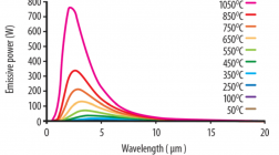
The figure shows typical Planck’s Law curves for a range of temperatures plotted from 1050°C to 50°C.
Note the wavelength - from 0 to 10 (intense) in micro meters.
Our sensor wavelength range is 760 to 1100 in nano meters
or 0.76 to 1.0 micro meters. Therefore, it is in the range of the shown curves.
Last edited:
ThanksVery nice with the feedback loop. What's your polling interval to cycle the power on and off?
I just put a counter in my program. For the period of 1.88 sec the power is switched on-off 950 times, based on the temperature readings.
Regarding the ZVS board - since there is no inrush current (like typical electrical motor) there is no danger for overheating.
Regarding overheating the body during 1.88 seconds interval - notice that the total heating power (in joules, if you will) is significantly less then the power (6 to1) appllied to heat the neck to 1000 F.
oliverpsmile what are you using to switch the power on and off to the ZVS board? Have you tested the switching speed. Some of those devices are slow, like 1ms to switch and many don't have specs at all. I asked a question about these clone no name SSR here.
The ones from known suppliers with specs to do the job cost over $40, no name ones from ebay and Amazon cost $10+. One has to wonder how well they really work.
e.g.
I'm now going to test just using one MOSFET to switch. I am using an air cooled double helix coil with and ID of 0.625. The coupling is so good that it melted a 44 mag case in just 3 secs. using only 28v at 20 amps. A much smaller power supply can be used, no water cooling needed but at a much reduced throughput. But if you have an auto feeder, auto temp control, who cares just load it up and walk away. Of course run it at a place that is fire resistant or outside just in case.
With the flame sensor and current monitor, program logic can be added to turn it off if any faults are detected.
Last edited:
SSR - 100DD - Solid-State-Relay-Module
You mean like these? It will probably work for the low duty cycle you are using the part for, but generally these are questionable.
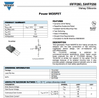
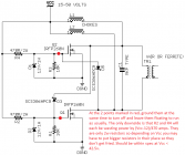
Thanks for pointing that out. I believe there is a way to ground out 2 points on the circuit board to use those existing MOSFETS as on and off switches.You guys realize that these "ZVS" circuit boards already have some high power solid state switches, right? This datasheet shows between 30 and 180 amps depending on conditions:
View attachment 1312398
Attachments
Similar threads
- Replies
- 74
- Views
- 47,364
- Replies
- 0
- Views
- 1,576
Upgrades & Donations
This Forum's expenses are primarily paid by member contributions. You can upgrade your Forum membership in seconds. Gold and Silver members get unlimited FREE classifieds for one year. Gold members can upload custom avatars.

Click Upgrade Membership Button ABOVE to get Gold or Silver Status.
You can also donate any amount, large or small, with the button below. Include your Forum Name in the PayPal Notes field.
To DONATE by CHECK, or make a recurring donation, CLICK HERE to learn how.

Click Upgrade Membership Button ABOVE to get Gold or Silver Status.
You can also donate any amount, large or small, with the button below. Include your Forum Name in the PayPal Notes field.
To DONATE by CHECK, or make a recurring donation, CLICK HERE to learn how.


