Follow along with the video below to see how to install our site as a web app on your home screen.
Note: This feature may not be available in some browsers.
This Forum is for adults 18 years of age or over. By continuing to use this Forum you are confirming that you are 18 or older. No content shall be viewed by any person under 18 in California.
Mr.Ulrich,
The science behind inductively testing metal structures for discontinuities is well understood and effective.
However, not so easy with a machine with the stability and sophistication of the Juenke machine.
I know some folks who have Juenke machines and some of them are very happy with them. I would guess that the high cost of them, then and now with the copies, is a reflection on the difficulty in properly tuning them both electronically and mechanically.
With the state of the art today, it would be way easier to get the stability and accuracy with either an inductive or a dynamic testing system.
Most people who want these systems are convinced that group flyers may be directly connected to discontinuities within the bullet, probably either in brass cladding thickness variations or air bubbles in the brass to lead interface.
After rereading the initial post I have some questions. you say bullets are dropping or dispersing a couple of m.o.a. and other shooters are experiencing the same issues are the shots mostly low. If it was a dynamic balance issue bullets would disperse in all directions not in one direction mostly.
Dispersion is spread but the low shots stand out for some reason and really bug me.
I see you dissect some bullets that you make for inspection and dont have a problem with air pockets. Thats good to hear and I have wondered about this anomaly happening in production bullets. Have you ever found air pockets in any bullet?
Even when examining dissected bullets that seem within spec, it still does not eliminate the possibility that the bullet is dynamically unbalanced. Logically it would certainly indicate a much less chance of imbalance if the bullet internals all look good.
Testing for dynamic balance is a lot easier than dissecting and measuring/examining bullets. It may well be a useful addition to the target shooters equipment list. It would provide another metric to check in sorting bullets for use in important competitions. Dynamic balance is a comprehensive test for things that remain unseen when inspecting, measuring and weighing bullets.
I would like to hear from any bullet manufacturer that actually sample tests their bullets for dynamic balance!
I know some folks who have Juenke machines and some of them are very happy with them. ( And I know many who hold world records and feel they are a waste)
Most people who want these systems are convinced that group flyers may be directly connected to discontinuities within the bullet, probably either in brass cladding thickness variations or air bubbles in the brass to lead interface.[/QUOTE]
(And some people pray over chicken feet) jacket t.i.r. not an issue maybe with factory but not custom. I have already had people test with railguns, the best .0001 against ,0007-,001 tir in tunnels and no one could tell in a blind test which was which.
Dispersion is spread but the low shots stand out for some reason and really bug me.
I see you dissect some bullets that you make for inspection and dont have a problem with air pockets. Thats good to hear and I have wondered about this anomaly happening in production bullets. Have you ever found air pockets in any bullet?
Even when examining dissected bullets that seem within spec, it still does not eliminate the possibility that the bullet is dynamically unbalanced. Logically it would certainly indicate a much less chance of imbalance if the bullet internals all look good.
The only place I could see an issue is when the lead crowns during pointing up, if it went off center somehow. but its also reduced to a smaller diameter so this would minimize any effect. I have not sectioned any factory bullets..
Admittedly I've only begun to think about this topic, but I assumed that the wobble you referred to comes from two-plane imbalance, not simple single plane imbalance.
That said, the chances of a bullet having two flaws creating equal and opposite imbalance seem impossibly low. So screening based on single plane imbalance certainly should help.
The general definition is two plane imbalance. Static unbalance results in what they call CG jump or lateral throwoff - that the CG of the bullet, not being in the center of hte bore is actually traveling in a helical path until the muzzle releases the bullet, which is then moving in a direction tangent to the CG's helical path. Dynamic unbalance will result in aerodynamic jump - the result of the bullet tipping on exiting the muzzle due to the principle axis of inertia being different than the bullet's geometric axis.
Both aerodynamic jump and lateral throwoff result in undesirable angular divergence of the bullet's initial flight path, although it's possible for the two to offset each other in some cases.
Pragmatically, as George says, it's probably best to just make good bullets rather than screw around trying to measure these tiny quantities. If they shoot well, they're balanced. Just keep doing that. Not that I'm against tinkering with this stuff- you never know what it will lead to.
Damon's pretty much has it correct I would add of the two aerodynamic jump would be a higher evil of the two. I agree on experimenting to move forward I think we're picking fly $h// out of pepper on this subject. If someone really wants to move forward I would look at our ignition system there is only maybe a half a dozen or so gunsmiths that even know where to look even less that can fix it to some degree...there are no action makers addressing these issues .
As I have said before in this thread, it was the 30cal, 230gr bullets that started me wondering about testing for dynamic balance. A group of us locally shooting these bullets from a few different magnums noticed the same regular flyers happening during matches. The shooters concerned were all experienced and capable of winning top level matches. The occurrence and number of flyers experienced at each match showed a similar pattern for all of us using this bullet. We stopped shooting it and changed over to the 215s. Wanting the gains of the high BC of the 230s I wondered if testing their dynamic balance would allow the flyers to be found.
One or two plane balancing for testing bullets where no action will be taken to correct the bullet's balance is academic. Locating the position of the imbalance is not required. All that's required to be found is if there is an appreciable difference in measured vibration magnitude between bullets. Obviously all bullets will vary slightly and data will need to analysed to find at what difference the bullet is deemed out of balance and prone to cause a flyer. Spin lots of bullets and measure their magnitude and look for regularly occurring spikes indicating imbalance. Run the results thru a spreadsheet and look at some statistics.
I gave up on this project when I could not build a test bed that would allow stable spinning of the bullets. I'm pretty sure I have a solution that holds the bullet concentrically and does not allow the bullet to move back and forth. I also started work on designing my own design software and interfacing a specific acceleromer with a digital SPI interface, etc.
For initial testing I will use a DynexHobby product and see if I can find any trace of imbalance before getting carried away using more sensitive sensors and custom design. Dynex provides a cheap Impulse branded hardware product and Platinum software to get the vibration analysis up and running. If any one else wants to try then follow the link and have a read of the User Manual for the Platinum software.
Not wasting time at all. I'm very interested to see what you come up with. I suspect it will be difficult to find the signal in the noise, but that's no reason not to try. At least then we'll know what doesn't work. As you've said, holding the bullet properly is really the hard part here.
I agree 100% with your statement and working out, (quantifying) what if any detectable imbalance causes the flyers. Initially I'm just looking for outliers.
I agree 100% with your statement and working out, (quantifying) what if any detectable imbalance causes the flyers. Initially I'm just looking for outliers.
I'll have it up and running next week, post pictures or a short video then!
Basically the belt drive system will be the same as in the video I posted previously. The change will be the adjustable T-Slot aluminium table that holds the bearings will be gone. In its place will be a small flat aluminium plate on soft vibration mounts with 2 marked and calibrated stainless steel rails. On these rails will slide the bearings holding the bullet under test.
Anyone with a basic skill set would be able to construct the device. If you use the DynexHobby vibration analysis kit, ($150) and some bits and pieces the project should cost under $500. I use a sensored brushless motor with a large speed control range which has a tacho pulse output. Hobby brushless motors and controllers would also do the job.
First to see if the thing can actually detect any imbalance with bullets. The background noise you mention should hopefully be able to be filtered out but you know what they say about things in theory!
I just finished putting the new test platform together and took a quick and dirty video with my phone.
The sensor is simply taped on to show the mounting position and I ran the motor up to 2700 rpm, (2" pulley) which translates to approx 17,500 rpm for the bullet.
Its an old beat up 230 gr bullet that has been used for some time in my other bearing supports that did not work as required. This new set up seems to run very well without belt slippage, (so long as speed is ramped up progressively).
Early days, and wont get to seriously test for balance until next week. Just posted this video to show the new bullet mounting and spinning method for those that are curious.
That's interesting - a very simple way to support it the bullet. One of those obvious-after-the-fact kind of solutions. But how do you swap out the bullets? Do you have to take it apart and re-align the bearings every time?
That's interesting - a very simple way to support it the bullet. One of those obvious-after-the-fact kind of solutions. But how do you swap out the bullets? Do you have to take it apart and re-align the bearings every time?
If you look at the calibrated SS rails, (cut up 6" rule) which are attached to the aluminium bed plate. Then look at the attach point of the bearing pillow blocks you will notice that rare earth magnets attach the blocks to the rail. The magnets in use are rated at 3.2kg each, (12.8kg holding the bullet under test to the rail) and you can push/slide them along the rail to take out and replace the bullet for testing.
Initially I tried using 5.5kg magnets but it was very difficult to even slide them along the rail. The 3kg magnets are ridiculously strong but can be moved sideways on the rail to enable bullet changing. Another one of those obvious after the fact kind of solutions.
Edit: Just another point worth mentioning in case its not obvious by observation. The bullet alignment is pretty much taken care of by the pillow blocks and bearings as they allow the bullet to self align concentrically between the centres. The bearings align, (make contact) on the tapered nose and boat tail, allowing self centering of the bullet. I have used the same id/od bearings at each end of the bullet.
The light aluminium pillow blocks, magnets and SS rail make the task of testing numerous bullets pretty straightforward. The graduated ruler rails mean you can easily align the bearings and bullet for every test. Moving the bullet and bearings together as they slide along the rail is a pretty cool and easy way to set up the bullet under the belt.
Now you can make your own and we can compare results for dynamic balance of bullets.
Edit: The bullets self align in the bearings as the two pillow blocks are slid together to hold the bullet. The bearings contact the tapered nose and boat tail of the bullet and self align concentrically without any skill being required to achieve it. Simple solutions are good solutions in my book.
Ah, now I see it. I really like the design so far. It keeps the rotating mass outside of the bullet about as low as possible, I would think. Please keep us up to date. I might try building one if you find that it works well enough. (I'm about 3/4 done with a powder trickling device that I want to finish before doing anything else, but this looks pretty simple to build once you figure out all the hard parts).
Does the DynexHobby software do everything you need it to, or will you need to write your own?
I will test the software this week, so I will be able to answer fully once tested. Its worth downloading the DynexHobby Platinum software and having a look at the "Advanced Vibration Meter" module, which is the icon depicting the large circular gauge. http://www.dynexhobby.com/software.html
I will be using the vibration meter in one window and have another window open in excel worksheet for me to input the vibration reading of each bullet tested. I'm thinking the DynexHobby should be able to do what I want, but either way I'll soon know after some testing.
I ran a few tests today with a modified 230gr bullet. I took off 0.5gr with the edge of a file by removing a little copper from two places on the same side of the bullet jacket. Thinking this would be enough to give an increase in vibration magnitude over the standard bullet.
Initially I got readings of about double the magnitude over the unmodified bullet. Problem is that it is not reliably repeatable over the noise of the sensor when the machine is running. The alignment and pressure of the bearings on the bullet plays a big part in the readings obtained.
The software worked fine and allowed be to set up filters, etc, but the readings always came down to how I placed the bullet in between the bearings. Pushing the bearings in toward the centre of the bullet increased the vibration level and pulling them apart allowed the bullet to run much quieter.
There is no way I can use this device as it is now to sort bullets into lots of balanced and unbalanced (outliers) the readings I'm getting are not reliable enough. So its back to the drawing board for one last attempt using a much softer cradle. The bearings work well and dont damage the bullet but are difficult to place for reliable/repeatable use in testing.
Can any bullet maker reading this give me their expert opinion on if a 0.5gr reduction on one side of the bullet is a reasonable amount to use for testing. How much variance in weight do you guys consider allowable for manufacture? It would be nice to have a guesstimate on what weight an air bubble in a lead core might be for the 230gr bullets. If I have a worst case scenario then I can use maths to work out what magnitude forces are in play and get some idea of the suitability of the accelerometer.
I wonder if using a preloaded spring to push one of the bearings would help even things out. But I'm concerned that even with filing the bullet you're having trouble finding the signal - I would expect realsitic defects to be more subtle. Most bullet boxes don't even vary by half a grain in my experience. Does the software have an FFT function? I wonder if there is any resonance in the fixture that's covering things up. The signal of interest ought to be at a predictable frequency.
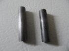
You might be best starting at the beginning and learning how bullets are made. I have included a photo of a formed cores there are NO AIR BUBBLES. this is the beginning of process and any inclusions will only become minimized more during core seating operation. Cores are generally held to .2-.3 grains MAX... Cut then formed in a press and excess is bled off to insure consistant weight .... Unless something is screwed up in core seating there will be no air. Next as I said I applaud your efforts but there are some problems with your set up. Bearings MUST be inline and 90* to each other. otherwise you will induce imbalance from an elliptical hole that bullet rests in. Bearings themselves all have vibration unless you bought see $$$$ class , I would recommend ceramic they are reasonably priced and a whole bunch smoother. Next you have no baseline to compare to, to check if you are getting vibration from belt,bearings or motor. I would buy a gage pin that correctly fits bearing bore and grind ends square then check to see what it picks up. This should give a reference to check from. continue on
This Forum's expenses are primarily paid by member contributions. You can upgrade your Forum membership in seconds. Gold and Silver members get unlimited FREE classifieds for one year. Gold members can upload custom avatars.